This site uses Google Analytics to make statistics on the pages consulted and to detect possible dysfunctions.
By continuing your navigation you accept that cookies can be deposited on your system (more information).
However, this site functions perfectly without cookies. You can therefore deactivate them.
It is certainly necessary to go back a long way in time to find the first motivations of the man who pushed him to send an object of any kind, but preferably blunt or sharp, on a fellow human being (act of war) or on an animal (act of hunting) with the aim of defense or aggression.
The main motivations were probably the impossibility of approaching the target (a fierce animal, for example) or the desire to stay at a distance from the target (a dangerous animal or adversary)
The entire history of ballistics can be summed up in one objective : to send a bullet as far and as accurately as possible at a target.
In this overview of ballistics, we will limit ourselves to talking about firearms, which are far from being the only way to send a bullet, since there are many devices that can serve this purpose.
Indeed, any system capable of transmitting its potential energy in the form of kinetic energy to a bullet can satisfy the need to reach a target placed at a certain distance. One only has to think of bows, crossbows, launchers using a spring, compressed air or even electrical energy which, in this last case, allows very high speeds to be reached.
In this presentation, we will limit ourselves to firearms and consider their ballistics classically broken down into three main parts:
- The internal ballistics of weapons that deals with the phenomena that occur in the chamber and barrel of the weapon until the exit of the bullet.
- The external ballistics which studies the aerial trajectory of the bullet.
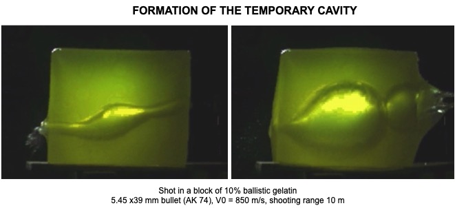
- Terminal ballistics which talks about the interaction between the bullet and the target. When the target is a living organism, or a dead one for that matter, we talk about lesion ballistics.
Very often, the external ballistics is itself split into two parts:
- Intermediate ballistics, which is interested in what happens between the muzzle of the weapon and a few tens of centimeters further on, at the moment when the bullet leaves the barrel. We will see that the universe in which our bullet evolves, fortunately briefly, is tumultuous and chaotic due to the action of the gases that expand and cause some damage.
- The external ballistics which begins at the end of the intermediate ballistics, when the gases no longer have any influence on the bullet, and ends when the bullet reaches the target, where the terminal ballistics begins.
Let's start at the beginning and talk a bit about the internal ballistics of weapons.
II - INTERIOR BALLISTICS OF WEAPONS
This is a complex field. Although the equations governing the behavior of gases inside the gun may seem perfectly abstruse to the uninitiated, it is however possible to understand, even if only qualitatively, this part of ballistics and to leave to the real specialists the pleasure of integrating their differential equations.
II-1 - BASIC CONCEPT
In firearms, the energy produced by the deflagration of an explosive substance, commonly called "powder", is used to propel a bullet. This substance, by definition, is capable of releasing its potential energy in a very short time, during a chemical reaction, in the form of a large quantity of gas at very high temperature. It is these gases that will propel the bullet out of the gun.
Before going any further, let's see, schematically, how a firearm works.
• A firearm is primarily a tube open at one end (usually)
Whatever its type and its external shape, a firearm is composed of a barrel which is nothing but a tube open at one end to let the bullet out, obviously. The opposite end, called "chamber" is where the explosion of the powder occurs. The back of the chamber is closed by a metal piece called a breech. On modern small arms, the sealing of this part of the barrel is mainly ensured by the ammunition case.
SIMPLIFIED PRINCIPLE OF A FIREARME
Figure II-1/1
• Cartridge
The evolution of techniques made it possible to gather the propellant charge, its firing system and the bullet in only one component : cartridge of which one will find a diagram below.
DIAGRAM OF A CARTRIDGE
Figure II-1/2
Below are some cartridge models and details of a bullet for modern weapons.
HANDGUNS CARTRIDGES SAMPLES
Figure II-1/3
CARTRIDGES FOR LONG GUNS
Figure II-1/4
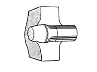
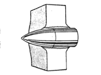
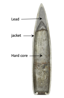
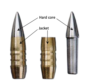
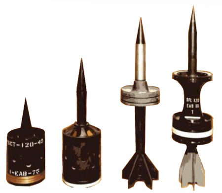
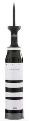
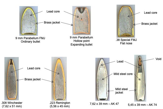
SOME TYPES OF BULLETS
Figure II-1/5
The bullets have various shapes and compositions depending on the nature of the target and the type of bullet/target interaction required, while respecting the laws of aerodynamics.
At the moment of the explosion of the powder charge, the gas pressure is applied on all the walls of the chamber and on the back of the bullet, the base, which, with a diameter practically identical to that of the interior of the gun, ensures a gas-tightness while presenting less resistance than the walls of the chamber. The bullet is thus pushed by the gases towards the mouth of the barrel according to the piston principle.
One will find, below, a diagram representing a cut at the level of the breech, chamber and beginning of the barrel with a cartridge at the time of the departure of the blow. The bullet has already taken the rifling.
LONGITUDINAL SECTION AT THE LEVEL OF THE BREECH
1) Firing pin - 2) primer - 3) flame jet from primer - 4) ignited powder - 5 case - 6) bullet
From : "Munition für Leoichtwaffen, Mörser
und Artillerie". Ian V. Hogg.
Motor Buch Verlag.
Figure II-1/6
• Weapon-munition matching
In the weapon/ammunition couple, the launcher (the weapon) is developed around the ammunition according to the following algorithm:
ADAPTATION OF THE GUN TO THE AMMUNITION
Figure II-1/7
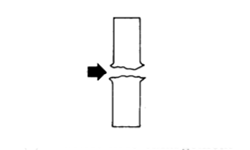
• Smooth barrel, rifled barrel
The internal part of the barrels, called bore, is generally presented in two forms: smooth or helically rifled, with constant or variable pitch. These rifling allow to apply to the bullet, during its course in the barrel, a moment of rotation with the aim of suppressing its erratic behavior during its course in the air.
SOFT BORE VS RIFLED BORE BARRELS
Figure II-1/8
• Shape of the bullets has changed with time... and the need of greater precision
In the early days of firearms, bullets were made of lead and were spherical in shape. A full and homogeneous sphere has a center which is, at the same time, geometric, of gravity and of symmetry.
The principle was simple. The inside of the barrels was smooth. The caliber of the cannon was not given according to its diameter, but rather, and this until about the 19th century, by the number of lead spheres that could be cast for the diameter of the cannon in an old pound of lead (489.5 g). This old habit is still found today for smoothbore shotguns. For example, the 12 gauge has a theoretical diameter of 18,5 mm and one could cast 12 spheres of lead for this gauge which is larger than the 16 gauge.
• The reason for the grooves
The first helical grooves are mentioned in 1476. Straight grooves are mentioned in 1498.
The ballistic experts of the time quickly realized the poor performance of smoothbore guns and their spherical lead bullets. The range of these weapons was poor and their accuracy decreased rapidly with distance. New solutions were needed.
During their journey in the smooth barrel, the spherical bullet, because of their design, were subjected to dissymmetrical friction forces that varied from one shot to another. They came out of the barrel with a rotational motion on themselves which, by interaction with the air, made their trajectory leave the shooting plane. They were endowed with an "effect" similar to that observed in ball games such as golf, tennis, soccer or other. The difference being that, in the field of sport, this effect is sought and controlled whereas in the old weapons it was random because the friction due to the interaction between the ball and the core of the barrel was not identical from one shot to the next. The idea was therefore, since there had to be an "effect", to foresee it by imposing a rotation, or not, on the bullet thanks to helical or rectilinear rifling. In the case of helicoidal stripes, the trajectory always went out of the trajectory but one knew from now on in which way and in which proportion. It was then enough to provide the sighting system with an abacus taking into account this deviation according to the range.
The idea of creating balls more aerodynamic than a sphere and with a more predictable trajectory led to the realization of bullets with elongated, oblong shapes and whose front has a more or less pointed profile.
One of the particularities of these bullets is that they do not have a center of symmetry but an axis of symmetry according to their length. When fired from a smoothbore barrel, they are perfectly unstable. They tilt or spin during their aerial trajectories.
Among the various methods of stabilizing a bullet, one chose to use the gyroscopic effect which transforms into a precessional motion the tendency of this bullet to tip over as soon as it leaves the barrel. For this purpose, it was necessary to make the bullet turn at high speed around its longitudinal axis. One thus traced helicoidal stripes in the core of the barrel in order to give it a rotational motion that it will keep throughout its trajectory. We will have the opportunity to evoke this stabilization by gyroscopic effect in the chapter "external ballistics".
Note : not all weapons that fire spin-stabilized bullets have a rifled barrel. Some of these weapons have a barrel with a polygonal rather than cylindrical bore.
• How a weapon works
When we talk about the functioning of a weapon, we are of course talking about launching a bullet but also, in the case of most modern automatic or semi-automatic weapons, ensuring its feeding.
The means of propulsion
The means that can provide a weapon with the energy necessary for its operation are varied. We can, for example, quote some of them:
- Compressed gas: air, nitrogen, helium or hydrogen depending on the desired speed. In addition to the air compressed weapons
, it is also a means of propulsion used in test gun of laboratories ;
- Compressed springs, rubber cords under tension ;
- Electricity. We use the force generated by an electromagnetic field ;
- Explosive substances.
It is the propulsion with explosive substances that is mostly used, hence the name firearms. If it is not the simplest, it has become the most practical and allows the operation of both high-powered weapons and others of low volume and easily portable.
The pressure of the gases generated by the combustion of the powder being the principal means used for the operation of firearms, we will stop one moment on this, or rather, on these powders.
II
- 2 - GUN POWDERS
Powders are explosive substances whose combustion reaction, i.e. the release of their energy, is sufficiently low (compared to other types of explosives) to be used for propulsion purposes. These substances are transformed according to the deflagration regime. Their linear transformation speed is of the order of a few hundred metres per second.
This explosive behavior is generally due to combustion, i.e. a redox reaction. The particularity is that, in this reaction, the oxygen necessary for the combustion is not mainly borrowed from the ambient air (the reaction would be too slow) but is integrated inside the powder, or even the active molecule. This particularity explains the speed of the reaction.
• The black powder
The Arab author Ab Allah was the first to mention saltpetre (13th century). Everything suggests that the Chinese invented it in ancient times and used it for fireworks.
Almost at the same time, Roger BACON, would have given a formula of the black powder.
The history leaves us with the memory of the German monk, Berthold SCHWARZ, who would have lost his life while trying to use it as a means of propulsion in the bombardes. A legend claims that the Devil still laughs about it.
Black powder is a mixture of potassium nitrate or sometimes sodium, sulfur and charcoal. The proportions of these various elements, ground very finely, being variable according to the desired vivacity, one should rather speak about "black powders".
History seems to have remembered the sad date, for France, of the battle of Crécy (1346) with regard to the appearance of black powder on the battlefield.
The English must have had two or three cannons that were noticed by the troops and the observers more for their noise than for their effectiveness, because, as the latter noted, once they had recovered from their emotions: "The Lord and the gentle Virgin Mary be praised, they did not hurt man, woman or child.
It was used for nearly five centuries, until Mr. VIEILLE invented smokeless powders (nitrocellulose powders).
Black powder is no longer used today except by sport shooters with antique weapons and by some manufacturers of rubber bullet cartridges. It should be kept in mind that black powder is relatively delicate to use. Indeed, it is an explosive substance whose transformation speed is of the order of 900 m/s, i.e. close to the limit that classically separates progressive explosives operating in the deflagration mode, of which powders are a part, and high explosives which transform themselves in the detonation mode. Depending on its confinement, black powder can pass quite easily from the progressive mode (deflagration) to the breaking mode (detonation) with harmful consequences on the material and, possibly, on the shooter and the close environment.
• Modern powders (called smokeless)
They are often referred to as "smokeless powders" although they are not powders and are not really smokeless.
In these propellants, the explosive properties of nitrocellulose, a substance obtained by the action of nitric acid on cotton, are used.
By nature, nitrocellulose is an explosive, and therefore unusable as is. To ensure slow combustion, control the speed and ensure good stability, nitrocellulose is gelatinized with an ether-alcohol mixture.
• Single and multi-base powders
There are two main families of smokeless powders: the "simple bases" and the "multibases".
In single base powders, the only active product is nitrocellulose. All other products in the composition are incorporated only to ensure stability and control of the burning rate.
In the family of multibase powders, we distinguish between "double base" and "triple base" powders. In these two types of multibase powders, nitroglycerin is added to increase the energy level of the powder.
Double-base" powders produce less smoke and have a better energy yield. However, they have the disadvantage of eroding the barrels more quickly because of their very high combustion temperature.
To overcome this disadvantage and to find the qualities of "single base" powders, while keeping the easy manufacture of "double base" powders, a third base, nitroguanidine, is added. We obtain a combustion temperature similar to that of the "single base" while keeping a great propulsive potential.
Figure II-2/1
• The "powders" are in the form of grains
Contrary to their name, powders are in the form of grains of various shapes. Combustion, and therefore the release of gases, takes place on the surface of the grains. It is easy to understand that the larger the surface of the grain, the greater the quantity of gas released in a given time. The shape of the grains of the powder, in addition to its chemical composition, greatly influences its vivacity, i.e. its speed of combustion.
• Influence of the shape of the grains
For a given amount of material, the geometric shape with the minimum surface area is the sphere. Starting from this lower limit, the powder grains are given geometric shapes with increasingly large surfaces (parallelepipeds, flakes, sheets, full cylinders, cylinders with a central hole or multiple holes along the longitudinal axis).
Its different shapes allow to have powder grains whose surface varies or remains practically constant during the combustion phase.
The powder grains must have good mechanical resistance because, during their combustion and pressure rise, they will be subjected to significant mechanical stress. They must not break, otherwise their shape will obviously be modified as well as their combustion speed and, ultimately, the vivacity of the powder.
• Powder ignition
The combustion of the powder is initiated by an ignition system. For small-calibre weapons, a primer placed in the base of the case is used. This primer contains a primary explosive which is by nature not very powerful, compared to other explosives, but which is very sensitive to shock and, in general, to external constraints.
Among the explosives used were lead styphnate, otherwise known as lead trinitroresorcinate, and mercury fulminate, which was relatively unstable and fell into disuse.
• Ignition mechanism
When the primer is struck by the firing pin, the deflagration of the explosive it contains projects high-temperature gases and incandescent particles that will ignite the powder. Hot gases will be emitted on the surface of the grains.
Ideally, all the grains of powder should be ignited simultaneously, the pressure in the chamber should rise rapidly to its maximum, remain there until the powder is completely burnt and then relax from that moment. Thus the speed of the bullet would be optimized.
In reality, this is not the case. A "smokeless" powder gives a pressure that increases progressively with time and remains at this maximum for a very short time.The combustion of the powder is never complete.
Moreover, there are pressure waves, originating in the regions where the powder ignites, which propagate to the limits of the case and the base of the bullet where they are reflected and can interfere at certain points. The pressure field in the chamber is not homogeneous and this very complex phenomenon can influence the mechanical stresses on the walls of the chamber or case and the burning rate of the powder grains.
In any case, after ignition, the pressure in the chamber increases and the hot gases push on the base of the bullet. The latter will not move as long as the force generated by the gas pressure on its base is less than that due to the static friction of its crimping on the case, which is an important factor in the initial rise in chamber pressure.
II-3 - PROJECTILE MOTION IN THE BARREL
From the ignition of the primer, it is interesting to study the temporal evolution of three phenomena in the chamber and barrel of a weapon.
As the pressure in the chamber continues to increase, the bullet begins to move forward and is faced with new friction that will present a resistance to its motion.
This resistance depends on the type of stabilization chosen for the bullet. For bullets stabilized by rotation, the most important resistance to advancement in the ballistic cycle will be the taking of scratches.
Indeed, in order to communicate to the bullet the rotation torque allowing it to reach its optimal rotation speed, the rifling of the barrel's core must, for small-calibre weapons, penetrate relatively deeply into its jacket. The shells, on the other hand, are equipped with a belt of ductile material, one of whose roles is to interact with the rifling of the barrel.
RELATIONSHIP BETWEEN PRESSURE AND BULLET POSITION
Military Ballistics - GM Moss, DW Leemines, CL Farrar
Figure II-3/1
The motion of the bullet results in an increase in the volume of the combustion chamber, a phenomenon that should lead to a decrease in pressure.
But the speed of combustion of the powder increases rapidly with the pressure and very high values are reached before the motion of the bullet. The result of these two antagonistic phenomena is the rapid attainment of the maximum pressure in the chamber. This maximum usually occurs shortly after the rifling is taken, whereas ideally it should occur at the moment of rifling.
CORRELATION BETWEEN PRESSURE, BULLET VELOCITY AND POSITION
Figure II-3/2
• Friction against the walls of the barrel
Since the bullet must be sealed from the tube core, friction is important. In rifled barrels, there is also friction between the bullet and the stripes. We generally consider three types of friction:
• Force required to take grooves ;
• Frictional force, metal/metal, due to the motion of the bullet in the barrel ;
• Friction force perpendicular to the wall of the scratches (for scratched barrels).
In the diagram below, the author breaks down the friction into its different components. For our part, in the following, for the sake of simplification, we will call FR the resultant force of all the friction which opposes the advance of the bullet. It is represented by a vector which is collinear to the force due to the gas but in the opposite direction
FRICTIONAL FORCES IN A RIFLED BARREL
Interior Ballistics of Guns - M. Krier, M. Summerfield
Figure II-3/3
The frictional forces are at their highest when the grooves are taken.
FRICTIONAL FORCE IN THE BARREL AS A FUNCTION OF THE BULLET TRAVEL
Military Ballistics - GM Moss, DW Leemines, CL Farrar
Figure II-3/4
• The parameters influencing the speed of the bullet in the barrel
Let's move on to the study of what happens in the gun and see the parameters that act on the motion of the bullet.
The phenomena, especially those concerning the production of gases and their actions on the bullet, are complex. The combustion of the powder is not instantaneous. Pressure waves propagate from the breech or from the bottom of the case towards the base of the bullet, are reflected there, go backwards while meeting others that propagate forwards, thus creating a phenomenon of standing waves whose distances between the nodes and the pressure bellies vary as the bullet advances.
The problem can nevertheless be simplified in part by considering on the one hand that gases constitute a continuous medium, i.e. that an infinitesimal element (particle) of gas contains a large quantity of molecules, and on the other hand by making the hypothesis of a uniform gas density from the breech to the base of the bullet. The experiment shows that this approximation is suitable for speeds up to 1000 m/s and we will see that it is useful when we want to have an idea of the kinetic energy of the gases at the exit of the gun.
Let's go back to our bullet and see to which solicitations it is subjected. These are forces. We have detailed the forces of friction. As we have seen, we add them together (vectorially) to obtain a resultant which we will name FR for force of resistance to the advance. It will be directed towards the rear and obviously opposed to the force FG due to the action, on the base, of the pressure generated by the gases, which is directed, it, towards the front. Our system of resultant forces could not be simpler: an FG force which tends to accelerate the bullet towards the front and another FR which will tend to slow it.
These two forces can, in turn, be added vectorially to give a resultant force applied to the bullet that we will call FP. Taking as positive the direction of the breech towards the muzzle of the weapon, we obtain a simple equation linking FP, FR andFG :
Equ. II - 3/1
Therefore, the above equation allows us to consider three cases:
• FG > FR : FP is positive. The bullet is accelerated. Its speed increases towards the muzzle of the gun ;
• FG = FG : FP is zero. As the bullet advances FG decreases. At a certain moment, very brief, we have the equality of the forces FR and FG. At this moment the acceleration is zero and the speed of the bullet is constant;
• FG < FR : FG continuing to decrease, if the barrel is long enough (too long), FR being greater than FG, the acceleration becomes negative. The bullet decelerates. It will leave the barrel with a lower velocity than it would have with a barrel of the right length. In the limit, the bullet would stop in the barrel.
The image below shows the simplified principle of a firearm with the three forces acting on the bullet.
SIMPLIFIED PRINCIPLE OF A FIREARME
Figure II-3/5
The friction in the barrel is not constant. They are particularly important at the time of the taking of stripes and their engravings in the jacket of the bullet or the belt if it is a shell. However, once this difficult passage is done, one can admit, without harming the generality, the hypothesis that they are constant, or take an average value, for the rest of the path in the gun. At our level, to consider them variable would complicate the problem unnecessarily and would not help the understanding of the phenomenon. Starting from these premises, we will determine the parameters which have an influence on the speed of the bullet once the rifling has been taken. Starting from the equation that we have just established linking FP, FR and FG, the calculations are not long and we will be able to detail them below.
When we start this kind of enterprise, we must know what we are looking for and where we want to go. In our case, we want to arrive at a relationship where the place of each parameter will allow us to understand how it acts on the exit velocity of the bullet. At this level of study, it does not matter to us how finely this parameter varies. The important thing is to understand how it acts globally. We therefore place ourselves in the perspective of a qualitative analysis. The quantitative aspect will eventually follow but, in this case, we will have to carry out measurements whose results will be integrated into the equations.
Simplifying assumptions
These hypotheses will allow, without detracting from the generality, to arrive at a relatively synthetic relationship concerning the parameters influencing the exit velocity of the bullet.
Hypothesis - 1 - Friction
We have seen that our study starts once the scratches have been taken and that from this moment we consider the friction as constant. We decide on this choice because, whether these frictions are constant or not, they slow down the bullet.
Hypothesis - 2 - The pressure in the barrel
As we have seen, the phenomenon is complex. We have already admitted the hypothesis that the gases constitute a continuous medium and have a uniform density from the breech to the base of the bullet. The force FG created by the action of the gases on the base of the bullet is of the form :
Equ. II - 3/2
Avec
L = length of the barrel ;
mp = mass of the bullet ;
Vp= velocity of the bullet ;
Pp = pressure at the base of the bullet ;
A = cross-section of the bullet base ;
xP = position of the bullet ;
PGmoy = average gas pressure ;
FGmoy = average gas force ;
FP = resultant force applied to the bullet ;
FG = orce due to the action of the gases on the base of the bullet ;
FR = force of resistance to the advance due to friction.
We do not know how the intensity of FG varies with time. What we do know, however, is that it pushes the bullet. How it pushes it, only pressure measurements would tell us, but in a global way, it pushes it. From then on, we can consider an average pressure in the barrel which is given to us by knowing the exit speed of the bullet and the length of the barrel. Physics gives us an equivalence relation between the kinetic energy of the bullet and the work of the average force of the gas:
Equ. II - 3/3
The above relation has the advantage that the average force* FGmoy can be really calculated as soon as the mass of the bullet, its muzzle velocity and the length of the barrel are known.
* We must be careful that introducing an average force implies de facto an average pressure. It is important to understand that these assumptions have only one purpose: to understand the phenomenon. These average values should not be used in the calculation of the strength of a weapon. Indeed, the averages tend to smooth the curves and to "plane" the peaks. The graphs above (Graphs 1 and 2) speak for themselves: the pressure peaks are high and it is from these that the resistance of the weapon must be defined.
It is useful to show the average force FGmoy as a function of pressure:
or with the average pressure
we obtain
Starting from the equation linking FP, FR et FG :
The second law of dynamics allows us to write :
By performing the following change of variable :
we obtain
Given that
The last equation can be written :
By integrating :
we obtain
and finally
The last equation allows us to obtain Vp
Equ. II-3/4
Or, if we want to show FGmoy :
Equ.II-3/5
This equation is the result of mathematical calculations. We must now use it in the context of physics, of ballistics. It is important to understand that it gives us information concerning the influence of certain parameters on the speed of the bullet at the muzzle of the weapon. It should not be considered as a function giving the variation of the speed of the bullet in the gun. Moreover, neither time nor distance appear in the equation. To put it simply, we should not ask too much of it. We can see its limits quite quickly:
• If FG > FR , all is well, we are in a context of normal operation of a weapon and we have a value of Vp ;
• If FG = FR, nothing abnormal ballistically since in this case FP is zero and Vp is zero ;
• The difficulty arises when we consider the case whereFG < FR. This is particularly the case when, in barrels that are too long for the power of the ammunition, the speed of the bullet passes through a maximum and then decreases. This phenomenon can be observed on some defensive bullet launchers available in "long barrel(s)" and "short barrel(s)" versions. In this case, our equation sends us into an imaginary world mathematically speaking. Indeed, in this case the term under the radical is negative and there is no solution in the set of real numbers. The domain of existence of our relation starts at zero and, with these preliminaries, we can see what information it gives us. But first let's see a simplification of this relation.
Simplification of the relationship
We can avoid this problem of the existence of a solution to our relation by freeing ourselves from friction. In our reasoning we assume that the force FG due to the pressure is greater than the friction. We thus arrive at a simplified relation of the following form, close to the first one :
Equ. II-3/6
If we analyze equation 2 or 3 mathematically, we can deduce that the higher the average pressure, the larger the cross-section of the base of the bullet and the longer the barrel, the higher the velocity of the bullet at the exit of the barrel. Conversely, the mass of the bullet acts in the opposite direction, i.e., with all the other parameters fixed, the higher the mass of the bullet, the lower the muzzle velocity.
If this equation is interesting for the understanding of the phenomenon, it is nevertheless necessary, as we have already said, to put it in the physical context, to define its limits in the ballistic sense and to analyze each of the parameters.
We will immediately settle the fate of the section of the base A and the mass of the bullet mp: these are constant values. Let us see the others.
The average pressure P cannot be constant. Even in the adiabatic regime (no exchange with the outside) the volume at the rear of the bullet grows as the latter moves forward and the pressure necessarily decreases, once all the powder is burnt (Graph II-3/2).
The length of the barrel L cannot be as great as one wants. There is an optimum length beyond which the force, generated by the gas pressure, which accelerates the bullet, becomes weaker than the frictional forces which tend to slow it down. Beyond a certain length of the barrel, the speed of the bullet decreases. It can even become zero, the bullet remaining in the barrel. This is why it is important to use the right powder liveliness according to the length of the barrel. One thus avoids a waste of energy (all the powder burns before the exit of the bullet) and, at the same time, the bullet leaves with its maximum speed (Graph II-3/2).
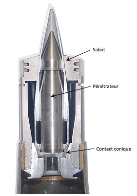
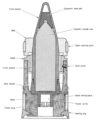
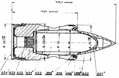
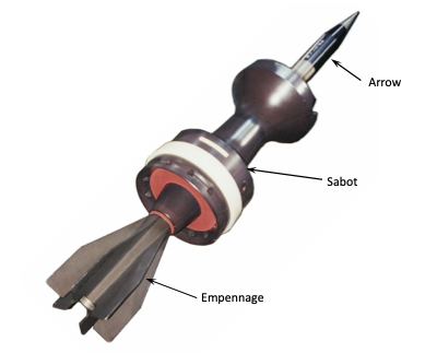
• Undercalibrated bullets
Let's go back to the section of the base A and the mass of the bullet mp. We can see that, all the other parameters being fixed, if we increase the cross-section of the base of the bullet while modifying its mass little or not at all, we obtain a higher muzzle velocity. This is the principle of sub-calibre bullets: the bullet is enclosed in a sabot made of a light material but with a large cross-section, and the whole thing is ejected at a much higher speed than the bullet would have reached on its own, if it had been fired in a gun of its calibre.
• Moment of inertia of the bullet and equivalent mass
Until now, we have considered the action of the FG force due to gases as advancing the bullet towards the muzzle of the weapon by fighting against friction. A more detailed analysis shows us that the FG force must actually fight against three oppositions :
1 - Frictional forces ;
1 - The force of inertia of the bullet whose mass opposes any modification of its translational motion ;
3 - The force of inertia of the bullet due to its moment of inertia which opposes its rotation.
We combine the two forces of inertia (displacement and rotation) by introducing an equivalent mass μ :
with
Equ. II-3/7
We obtain the force equation :
Equ. II-3/8
with "a" the acceleration of the bullet
• Projectile rotation speed
On its trajectory the stability of the bullet is ensured by gyroscopic effect. It is spinning in the barrel by the rifling.
The speed of rotation ω at the muzzle of the weapon can be obtained using two formulas. One or the other is used depending on whether the pitch of the rifling or its angle α to the bore axis is known.
or
Equ. II-3/9
Let us specify that the acceleration of rotation exists as soon as the scratches are taken. It is not necessary that the bullet has covered a distance equivalent to one step of the rifling to have its definitive speed of rotation. Moreover, in the formulas above, the length of the barrel does not intervene. Clearly, two bullets having the same muzzle velocity have the same rotation speed whether they are fired into a 2 inch or 4 inch barrel as long as the two barrels of different length are rifled at the same pitch, for example 25 cm.
• Linear momentum of the bullet and gases at the weapon's mouth
The linear momentum of the bullet and the gases at the muzzle of the weapon are the two main factors involved in the recoil phenomenon of the weapon. When we talk about these linear momentums "at the muzzle", we mean just before the bullet leaves the barrel. In this case, the part of the gas stream at the base of the bullet has the same speed as the latter.
- Linear momentum of the bullet
Product of the mass of the bullet Mproj by its velocity Vprojj at the mouth, it is easy to calculate when we know these values.
Qproj = Mproj x Vproj
Equ. II-3/10
- Linear momentum of gases
The problem is more delicate. Contrary to the calculation of the linear momentum of the bullet which is easy because we know, by measurement, its speed at the mouth of the weapon, we cannot measure the speed of the gas stream. We will deduce it from that of the bullet.
If we want a calculation that is not too complicated, we must consider some simplifying assumptions. Indeed, an analysis of what happens in the gun behind the bullet leads us to the following observation. We keep the simplifying hypothesis of the homogeneity of the gas stream and we cut it, perpendicularly to the axis of the gun, into very thin slices ; we split this gas stream into slices as thin as we want and we see what happens. It is clear that the slice of gas in contact with the breech of the bullet has the same speed as the latter, but the slice of gas in contact with the breech or the bottom of the case has a zero speed. Between these two extreme slices, all the others have a different speed according to their position in the barrel. The problem thus seems complicated.
We solve this problem by considering not the velocity of each of the gas slices but that of the center of gravity of the gas stream. The position of the center of gravity of the gas stream must be known since it is its variation which gives its velocity. The position of the center of gravity of the gases depends on the distribution of their volume, which leads us to consider two cases: the case of the guns with chamber and the case of the guns without chamber.
In interior ballistics a distinction is made between two types of guns :
1 - Barrels with a chamber : the end of the barrel containing the powder, the cartridge, is of a diameter greater than that of the barrel. This is generally the case with powerful weapons, notably most rifles, but also with certain automatic pistols firing what is commonly called "bottleneck cartridge ";
2 - Chamberless barrels : the end of the barrel containing the powder, the cartridge does not have a diameter significantly different from that of the barrel. This is the case for example with revolvers and some automatic pistols such as those firing 9x19 mm ammunition.
Let's start with the simplest.
1 - Chamberless barrels
A barrel without a chamber can be considered as a cylinder. The volume distribution being symmetrical with respect to the middle of the cylinder, when the bullet reaches the muzzle of the barrel, the center of gravity is in the middle of the barrel.
The calculation is not very complex and we present it below.
Noting :
Qg = gas momentum ;
xg = position of the center of gravity of the gas ;
x = position of the base of the bullet ;
Vxg = speed of the center of gravity of the gas at the point xg
;
mg = mass of the gas ;
ρ = density of the gas ;
A = area of the base of the bullet ;
VP = velocity of the bullet ;
QP = bullet momentum.
The momentum of gases is given by the relation : Qg = mg x Vxg.
Introducing ρ the density of gases and considering the variation of the position of their center of gravity, we obtain:
In chamberless barrels, the linear momentum of the gases at the muzzle is equal to the product of the mass of the gases by half the speed of the bullet.
Equ. II-3/11
Intuitive method
We can consider an intuitive reasoning to arrive at the same result.
Let's replace the gases by a spring as propellant. The coil of the spring in contact with the base of the case is animated by the same speed. The velocity of the coil at the bottom of the firing bowl is zero. At a given moment, the speed of each of the coils increases from the breech to the base of the bullet. When the latter reaches the muzzle of the weapon, the middle coil, where the center of gravity of the spring is located, is considered to be well balanced and has covered half the distance covered by the base of the bullet, and its speed will also be half that of the bullet (see diagram below).
GAS MOMENTUM (Alternative thinking)
Figure II - 3/5
2 - Case of barrels with chamber
In barrels with a chamber, the distribution of the gas volume is not symmetrical due to the very presence of the chamber. When the bullet reaches the muzzle of the weapon, the center of gravity of the gases is behind the middle of the barrel. It has travelled less than half the distance covered by the bullet. It therefore has a speed of less than half that of the bullet.
There is no general formula giving the velocity of the gases when the bullet reaches the end of the barrel since the distribution of the gas volume is specific to each weapon. However, measurements carried out on various weapons make it possible to give orders of magnitude : let VCG be the velocity of the center of gravity of the gases when the base of the bullet reaches the muzzle of the weapon and VP the velocity of the bullet at the same moment, VCG is of the order of 0.46 to 0.47 VP instead of 0.5 VP in barrels without a chamber. The difference is minimal but it exists.
• Kinetic energy of gases
The table below gives the energy balance classically used during a shooting.
THE APPROXIMATE DISTRIBUTION OF LIBERATED ENERGY
Military Ballistics - GM Moss, DW Leemines, CL Farrar
Figure II - 3/6
It can be seen that the amount of energy distributed in the gases, either as heat or as kinetic energy, is significant.
It can be useful to know the kinetic energy of the gases at the mouth for various reasons, for example to have an idea of their lesion potential. It is known that a close contact shot to the skull with a blank bullet is likely to result in serious injury or death.
To obtain the kinetic energy of the gases at the muzzle of the gun, it is classic to start from the Lagrangian gas continuity equation, which allows one to know the distribution of the speed of the gases behind the bullet :
We assume a uniform density of gases from the breech to the base of the bullet :
Integration of the Lagrange equation gives a result of the form :
Kinetic energy of gases :
If this relation presents a sympathetic aspect, it is not completely right. Indeed, beyond 600 m/s the density of gases begins to be no longer uniform. We have to introduce a coefficient δ in order to obtain the following expression:
Kinetic energy of gases :
Equ. II-3/12
Up to a speed of 600 m/s, we take δ = 3. Beyond that, we refer to figure II - 3/7 below:
VARIATION OF δ AS A FUNCTION OF BULLET VELOCITY
Interior Ballistics of Guns - M. Krier, M. Summerfield
Figure II - 3/7
It can be seen that up to 1000 m/s, δ varies slightly and that for conventional small arms, the gas velocity at the rear of the bullet is about one-third that of the bullet.
The mathematical solution of the problem of the kinetic energy of the gases at the weapon's mouth is relatively long. The interested reader can find here the calculations.
• Gun recoil
We cannot close the chapter on domestic ballistics without addressing the phenomenon of gun recoil.
It is accepted that gun recoil is due to three components :
1 - Momentum of the bullet ;
2 - Momentum of gases ;
3 - Muzzle blast.
Points 1 and 2 have just been discussed and allow us to pose the following equation:
Equ. II - 3/13
The sign "-" in front of the second member indicates that the sum of the quantities of motion of the bullet and the gases is in the opposite direction to that of the weapon and that the sum of all the linear momentums is zero, which it was for the system before the shot was fired.
Point 3 is more difficult and deserves our attention because experiments show that the contribution of the impulse due to the blast of the gases released at the muzzle can reach nearly 30% on certain powerful weapons such as war rifles in 7.62 x51 mm calibre. This is the reason why muzzle brakes are so useful.
We can try to solve this problem by looking at the functioning of the nozzles which has been well understood for a long time. We can thus say that the thrust exerted at each moment on the weapon by the ejected gases is given by the equation :
Thrust = Net Gas Pressure at Exit x Exit Area x Mass Flow
Equ. II - 3/14
Even before studying this equation briefly, we must be suspicious because this relationship describes the operation of a nozzle in a steady state, whereas the phenomenon we are interested in is transient.
The application of this equation to our particular problem of weapon recoil leads us to the negative conclusions reached by other ballistic experts interested in this phenomenon :
The Net Gas Pressure at Exit is simply the average gas pressure at the muzzle minus the atmospheric pressure. The pressure in the barrel before the bullet exits is several hundred bars. It drops to zero in a fraction of a second, this rate of change, necessary for our study, is unknown and all the figures that we could use could only be conjectures.
The Area of the Exit, which is the cross section at the mouth of the gun is easily calculated from the diameter, known, of the gun.
The Mass Flow is, like the Net Gas Pressure at Exit, unknown as far as our recoil calculations are concerned.
Finally, all this equation tells us is that the higher the atmospheric pressure, the lower the recoil of the weapon due to the muzzle blast, and that the higher the atmospheric pressure, the lower the Net Gas Pressure at the exit is. Indeed, it is easy to understand that if the ambient air is at the same pressure as the gases inside the gun, the gases will not come out at all and the recoil due to this effect will be zero.
The above equation does not bring us much information about our problem. Let's turn to the literature.
The specialized books give divergent values of gas exit, going from 670 m/s (Kneubuehl) to 1500 m/s for other authors (Engineer General Moreau). In their defense, these values depend on the caliber, the type of powder and the power of the weapon. Only Kneubuehl specifies that the value given concerns the 9 mm Luger and that for the .38 Special the speed of exit of gases is 930 m/s.
A calculation carried out from the half angle at the top of the Mach cone at the rear of a bullet (gas/bullet nose interaction) at the exit of the barrel, the average speed of the gas stream and the speed of sound in the gas volume at a temperature of 1200 K, gives us an initial gas ejection speed of 1013 m/s for a bullet with a muzzle velocity of 330 m/s. Taking into account the uncertainty of the measurements this calculated value is to be taken as an order of magnitude.
It seems that on this subject the theory shows its limits and that it is towards experimentation that one must turn.
By measuring the speed of recoil of the weapon Vgun during a shot and knowing its mass Mgun, we easily obtain its linear momentum Qgun. It is the same for the linear momentums of the bullet Qproj and of the gases Qgas. If we call Igas the impulse due to the gas, its value is given to us by solving the equation below :
Igas = Qgun - (Qproj + Qgas)
Equ. II - 3/15
We stayed for a while at the mouth of the weapon. Let's move forward a little and observe the exit of the bullet from the barrel. We enter the field of intermediate ballistics.
But before going any further we are in a situation where we have a bullet which, through the transformation of a chemical potential energy into a kinetic energy, is endowed with a capacity to perform mechanical work on a target. We know that it is also animated by a linear momentum capable of being transmitted violently. Which of the two criteria should be chosen to evaluate its efficiency: kinetic energy or momentum*? The diagram below gives us some guidelines.
*Answer : the kinetic energy of a bullet gives it the capacity to do mechanical work on a target. This mechanical work will be all the more important as it will be well used. It is therefore the kinetic energy that is the criterion for the effectiveness of a bullet. Even if many theories have been developed on the stopping power, kinetic energy remains the only truly scientific criterion used in ballistics laboratories.
Let's expand on the subject a bit.
• Kinetic energy versus linear momentum. The example of the ballistic pendulum
Energy and linear momentum are two physical quantities that are subject to the law of conservation. In other words, in classical, Newtonian mechanics, they cannot be created ex nihilo, nor can they disappear.
Energy can be conserved, but it can also be presented and transformed into different forms of energy. This is particularly true of kinetic energy, which can be transformed into other types of energy during an interaction.
Linear momentum, on the other hand, can only transmit motion.
These particular properties of energy and momentum are illustrated in the figure below.
Figure II - 3/8
Example of application with the ballistic pendulum
Nowadays, projectile velocity is precisely measured using a variety of devices, including ballistic chronographs and Doppler radars.
Before the advent of these sophisticated devices, the principle of the ballistic pendulum was used. The device could consist, for example, of a container filled with sand, with the front face sealed by a thin sheet of lead. With a few experimental precautions, such as firing at the device's center of gravity and a small angle of rotation α of the pendulum, the projectile's impact velocity could be deduced with good accuracy from the height hp = h1-h2= h1.(1-cos α) reached by the pendulum ; see the two figures below. This method of measurement is a good example of the use of kinetic energy and momentum.
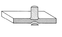
Pendulum at rest before impact
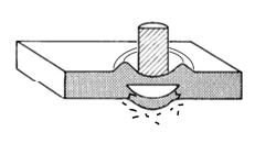
Pendulum after impact
Figure II - 3/9
Solving the problem
On impact, the projectile's kinetic energy is distributed between various phenomena: displacement of the sand, heat, possible deformation of the projectile, displacement of the pendulum and so on. The equivalence between kinetic energy and potential energy cannot be used to directly deduce projectile velocity.
The problem can be solved in three stages.
Step 1 : Calculate the initial velocity of the pendulum due to impact.
Knowing the height hp reached by the pendulum and its mass mp , we can determine its initial velocity vp. We use the equivalence relation between kinetic energy and potential energy.
Step 1 gives us the initial velocity of the pendulum vp just after impact :
Equ. II - 3/16
Step 2 : Calculate the pendulum's linear momentum due to impact.
Knowing the pendulum's initial velocity vp, calculated from equation II - 3/16, and its mass mp, we can determine its momentum Qp.
Equ. II - 3/17
Step 3 : Calculation of projectile velocity vproj at impact.
According to the principle of conservation of linear momentum, the linear momentum of the pendulum Qp is equal to that of the projectile Qproj which impacted it. So, knowing the linear momentum of the pendulum Qp, we also know that of the projectile Qproj , from which we can deduce the velocity vproj at the moment of impact.
Numerical application
An 8 g projectile is fired at a ballistic pendulum made of sand, with a total mass of 5 kg. The pendulum reaches a height of 5 cm from its initial resting position.
What is the speed of the projectile at the moment of impact ?
(We'll neglect the weight of the pendulum suspension and the energy of rotation).
Answer
Step 1 : Calculate the initial velocity of the pendulum vp due to impact.
Step 2 : Calculate the pendulum's linear momentum Qp due to impact.
Step 3 : Calculation of projectile velocity vproj at impact.
Since the momentum of the projectile Qproj is equal to that of the pendulum Qp, we obtain :
Note : Only in the ideal case of a perfectly elastic shock (no loss of energy) does "kinetic energy -> kinetic energy". Hence the need to know how to choose the right tool at the right time and according to the phenomenon.
We shall see that, in certain other cases, the use of linear momentum is also relevant.
III - INTERMEDIATE BALLISTICS
A bullet in the storm
It should be noted that some ballistic experts, and not the least, make no distinction and do not speak of intermediate ballistics. They consider that, as soon as the bullet leaves the barrel, it is a question of external ballistics and that what happens at the muzzle of the weapon is an epiphenomenon that emphasizes the need for good stabilization, which is true in the literal sense of the term. We do not advocate any particular method but, considering the interesting phenomena that take place there, we have decided to treat this initial phase of external ballistics separately.
The intermediate ballistics corresponds to the initial phase of the flight of the bullet during which the gases still exert an action on the latter.
During its path in the barrel, the bullet plays the role of a piston and the speed of the gases behind it is limited by its own speed, provided that there is a good seal between the bullet and the inner wall of the barrel. This is not always the case in practice. It often happens, in fact, that some of the combustion gases precede the bullet at the muzzle of the barrel, as shown in the video* below.
GASES AT THE MUZZLE
Figure III - 1/1
The sequence is detailed in the image below.
IMAGE SEQUENCE OF GASES AT THE MUZZLE OF BERETTA 92F
tr>
Figure III - 1/2
At the exit of the gun, the gases relax and, no longer blocked by the base of the bullet, accelerate and overtake it.
At the very beginning of this phase, the difference in speed between the bullet and the gases is such that a shock wave is created at the base. This phenomenon is very clear in high speed shooting, as shown below, the video* and the sequence of images.
GASES AT THE MUZZLE
Figure III - 1/3
The sequence is detailed in the image below.
IMAGE SEQUENCE OF GASES AT THE MUZZLE OF RUGER SP 101
Figure III - 1/4
We are in the same situation as if the bullet was moving in the gas with the base forward and at a supersonic speed.
The bullet is subjected to two major constraints :
1 - The brutal encounter with the ambient air which is called initial percussion ;
2 - The gases that exert a thrust on the base.
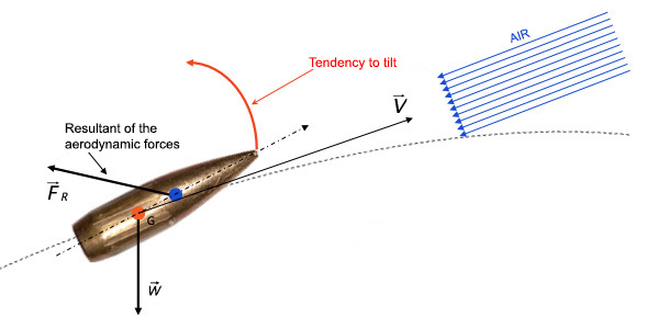
When the bullet leaves the barrel, its longitudinal axis is never perfectly aligned with that of the barrel. Due to the combined actions of the initial percussion and the gases, it is subjected to a couple of forces that tend to make it tip over.
The diagram below represents the situation.
GASES AT THE BULLET BASE
Figure III - 1/5
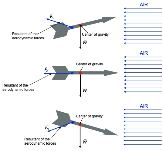
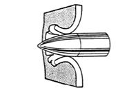
• The consequences of the action of gases on the bullet
Below, we see the normal behavior of a bullet designed to be stable in relation to the medium, the air, with which it interacts.
NORMAL BEHAVIOR OF A BULLET
Figure III - 1/6
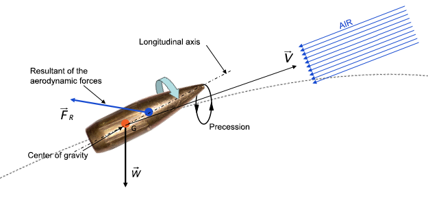
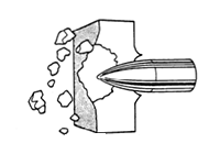
The following image shows us the situation in which the bullet is subjected to the action of gases.
EQUIVALENT BEHAVIOR OF THE BULLET IN GASES
Figure III - 1/7
It is during this phase that the effectiveness of the stabilization is crucial.
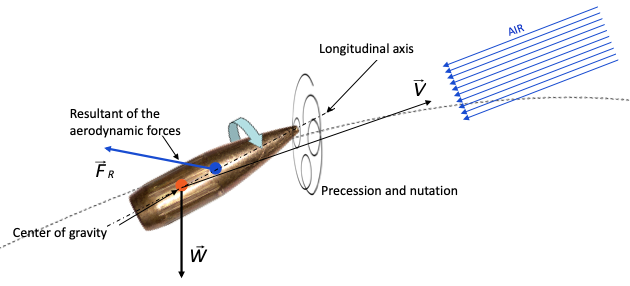
The phenomena at the mouth of the weapon are schematized below.
SCHEMATIC PRESENTATION OF THE PHENOMENA AT THE MUZZLE
Figure III - 1/8
The stabilization of the bullet having been effective, it leaves this agitated region to approach the air phase of its trajectory. We enter the external ballistics.
IV - EXTERNAL BALLISTICS
• The two approaches to external ballistics
Classically, the study of external ballistics is subdivided into two parts :
1 - Ballistics in vacuum : the only force acting on the bullet is its weight ;
2 - Ballistics in the air : we take into account the interaction of the bullet with the medium in which it propagates, the air.
IV-1 - BALLISTICS IN VACUUM
The bullet is subject to only one force : its weight.
It is animated by a velocity whose representative vector, V, tangent to its trajectory, generates a plane, the shooting plane.
This velocity vector V can be decomposed into a horizontal and a vertical component:
The horizontal component along the x-axis:
Equ. IV-1/1
The vertical component along the y-axis:
Equ. IV-1/2
With α the angle of fire.
Figure IV-1/1
• Forces applied to the bullet
We have decomposed the motion of the bullet into two components along the x and y axes. To study this motion on the trajectory, we will define the forces that apply on these components.
Depending on x :
Equ. IV-1/3
Depending on y:
Equ. IV-1/4
With, for the two equations :
We remind the equations of uniformly accelerated motion since, in our case, this is what it is all about :
Figure IV-1/2
• Interpretation of the force equations depending on x and y
Depending on x, the force Fx is zero so the acceleration is zero, the change in motion is also zero. There is no air or any other friction to modify the motion in this direction. It could continue indefinitely, identical to itself, as long as the bullet does not encounter an obstacle.
Depending on y, the force Fy is not zero. As for the horizontal component, there is no air and no friction. But there is the weight of the bullet which is a force. It acts on the vertical component of motion. We can also say that it acts differently according to the phases of the trajectory. It slows down during the ascent, so much so that at a certain moment the vertical speed is cancelled, then accelerates the motion during the descent in such a way that, for the same altitude, the speed of the bullet is identical during the ascent and the descent, but in the opposite direction. This explains why, when shooting on horizontal ground, the arrival speed is the same as the initial speed, both in its intensity (its modulus) and in the value of its angle.
The only force modifying the motion along the vertical is the weight of the bullet which is the product of its mass and the acceleration of gravity g. We consider that g does not vary on the trajectory. This is a good approximation if one is not an artilleryman and if one does not send bullets in curved shots several tens of kilometers away. We are therefore, in the vertical direction, in the case of a uniformly accelerated motion.
All the initial parameters such as the speed Vo, the angle of fire, the weight of the bullet (considering that g does not vary on the trajectory) are fixed at the start of the shot. They will not vary during the flight of the bullet. We can represent the trajectory by a generalized equation.
• Generalized equation y = f(x)
Table IV-1/1 gives us the variations of y as a function of time. It is the result of the application of the second law of dynamics F = m x dv/dt which, by double integration gives us y = f(t). Following the same process, the table also gives us x = f(t). We have :
Equ. IV-1/5
and
Equ. IV-1/6
Equations IV-1/5 and 6 are the general equations that we will adapt to our situation and simplify at the same time. The acceleration a is replaced by the acceleration of gravity g. We have seen that g has an action only on y. We simplify the equations by taking x0 = y0= 0, that is to say that we study the motion from the mouth of the weapon whose coordinates are x0 = 0 and y0 = 0. We obtain:
Equ. IV-1/7
and
Equ. IV-1/8
The sign "-" means that g, a vector quantity, is opposite to the direction of motion.
At this time we have information on the values of x and y as a function of time t. Very often, it is useful to know the trajectory as a function of the distance x, i.e. in the form of a function of the type y = f(x) which we will obtain thanks to a simple transformation.
En posant t = x / Vcosα et en injectant cette valeur à la place de t dans l'équation de y, nous obtenons, après quelques arrangements, l'équation générale de y en fonction de x.
By positingt = x / Vcosα and injecting this value in place of t in the equation of y, we obtain, after some arrangements, the general equation of y as a function of x.
Equ. IV-1/9
This is the equation of a parabola. By reducing the bullet to its center of gravity, we can draw a curve of its trajectory.
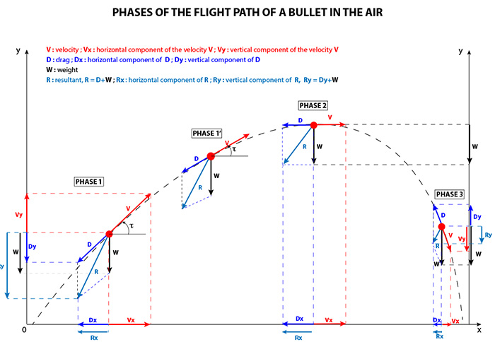
PHASES OF FLIGHT OF A PROJECTILE IN VACCUUM Parabolic trajectory
Figure IV-1/1
For the clarity of the diagram IV-1/1, the bullet is reduced to its center of gravity G.
The only force to which the bullet is subjected is its weight W.
The horizontal component Vx of the velocity V is constant. Only the vertical component of V, Vy varies.
V varies because Vy varies. Under the action of W, Vy decreases in ascending phase (phase 1 and 1').
Vy is zero at the apogee of the trajectory and V is minimum (phase 2).
During the descending phase (phase 3), under the action of W, Vy increases, as does V.
At the same altitude, the value of V is identical in modulus but of opposite direction.
The final speed is equal to the initial speed.
Continuing our study, we will determine on this parabola a certain number of characteristic points. Cf. diagram IV-1/2, below :
FIRING IN VACUUM Firing parabola Characteristic points
Figure IV-1/2
• The parabolic path
Figure IV-1/2 above shows a parabolic path and its particular points giving the distance and time to reach them.
The line (D) is the director of the path parabola and the point F its focus.
The circle with center O and radius A is the locus of the foci of all path parabolas for the same initial velocity Vo and variable shooting angle α.
The tangent (T) is the bisector of the angle AOF.
The point P is the characteristic point of the envelope of the shooting parabolas under variable shooting angle and constant Vo . It is the parabola having for focus the origin and for vertex the point A.
For a given initial speed Vo, all the points of the plane under the envelope of the shooting parabolas can be reached by two shooting parabolas corresponding to two shooting angles.
The points of the plane outside the envelope of the shooting parabolas cannot be reached. This is why the envelope of the shooting parabolas is called the safety parabola.
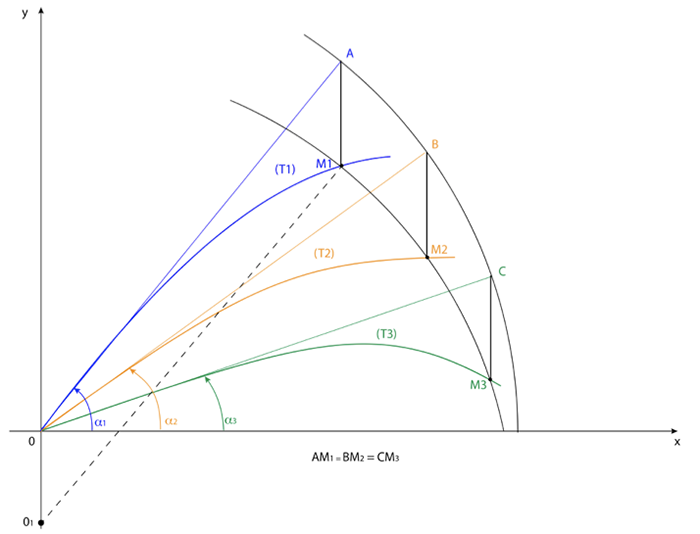
• Firing parabolas
On the diagram IV-1/3 below appear firing parabolas for different angles of firing for the same initial speed. One notes, in particular, that the targets, T1, T2, T3 and T4 can be reached by two parabolas having different firing angles. In a general way any point of the plane under the safety parabola can be reached by two firing parabolas. This can be of practical interest, as the same target can be reached by a relatively low parabolic trajectory or by another one whose higher apogee allows, for example, to pass over an obstacle. The red curve represents the maximum range with a 45° firing angle.
FIRING PARABOLAS
Figure IV-1/3
• Define two shooting parabolas for the same target with the same initial speed - Geometric method
On the diagram IV-1/4 below, we propose to reach the target (red point)T, which is on a first shooting parabola (blue), with another shooting parabola (green).
The start of the shot is at 0. The focus F1 of the first parabola (Shot 1) is on the circle C1 centered at 0 and tangent to the directing line (D).
The target T is, by definition, at equal distance from F1 and from (D). It is thus the center of a circle C2 tangent to (D).
The two circles C1 and C2 intersect at F1, focus of the first parabola (Shot 1) and at F2, focus of the new parabola (Shot 2). The tangent (T2) is bisector of the angle A0F2, which allows us to find the new angle of fire.
HOW TO DEFINE TWO SHOOTING PARABOLAS
Figure IV-1/4
IV-2 - BALLISTICS IN AIR
• The problems of external ballistics
During its flight path, the bullet is subjected to a certain number of constraints which give rise to a system of forces. Some of these forces have a strong influence on the trajectory while others have a lesser effect. In the case of relatively short trajectories, such as those of small-calibre bullets, some of these effects are non-existent and we can ignore them, while others, because of the reduced flight time, do not have the time in practice to act in a significant way. The constraints to which the bullet is subjected have been classified into two categories : the main problem and the secondary problem.
• The classification of problems in external ballistics
The forces acting on the bullet have been classified according to the importance of their influence on the trajectory.
1 - The main problem :
- The gravity supposed constant in intensity and direction (weight of the bullet) ;
- The tangential resistance of the air.
2 - The secondary problem :
- The Earth(sphericity, rotation);
- Gravity (variation with altitude and longitude, convergence of verticals) ;
- The atmosphere (variation of density with altitude, atmospheric wind) ;
- The bullet (gyroscopic drift).
As we are particularly interested in the ballistics of small arms, we will limit ourselves mainly to the study of the main problem. The study of the gyroscopic drift will nevertheless be of interest in order to determine its influence on long range shots.
• The main problem
During the whole phase of its flight, the bullet is subjected mainly to two forces: the force of gravitation which makes it fall towards the center of the Earth and the drag force, the retardation, due to the air in which it moves, which slows it down and prevents it from going as far as if it were shot in a vacuum.
We have seen previously that the first bullets were spherical. Very quickly, it was realized that this shape was not the best in terms of aerodynamics and precision. Therefore, the need to manufacture more streamlined bullets became apparent.
However, in order for this to work, the bullet must move with its nose forward and its longitudinal axis must be tangent to its trajectory, which is not necessarily obvious.
• Trajectory and range
If we were to shoot in a vacuum, that is to say if there were no atmosphere, our bullet would describe, as we have seen, a parabola. In reality, it would describe an ellipse whose one of the foci would be the center of the Earth. It would describe a circle around the center of the Earth for a precise speed but, taking into account its initial speed, in practice too weak, it would end up meeting the surface of our planet.
Its range would be much greater than it is in the air. A war rifle bullet fired at an angle of 45 degrees (maximum range in a vacuum) would hit the ground several tens of kilometers away.
To get an idea of the shape of a firearm bullet's trajectory, let's look at a golfer's drive or a soccer player's shot. It starts out straight, then quickly curves and falls to the ground very steeply.
The trajectory of a bullet is much flatter, but the shape is the same.
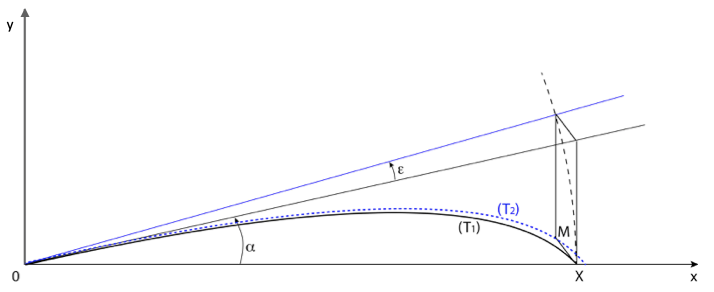
Figure IV-2/1, below, gives an idea of the difference between a shot in a vacuum (curve A) and a shot in the air (curve B). If it is the same bullet, (the two curves on the graph are not to scale), the trajectory A is about ten times shorter than that described in B.
Figure IV-2/1
IV-3 - DRAG SLOWING - RETARDATION
The bullet is slowed down by the air in which it propagates. This braking, called "retardation", depends on many parameters such as: the mass of the bullet, its maximum diameter or master torque, its shape.
IV-3-1 - BRIEF HISTORY
The laws of slowing have evolved with time, the increase in the speed of the bullets and the better understanding of aerodynamics.
Historically, the experiment had highlighted three laws :
- The air resistance is proportional to its density;
- The air resistance is proportional to the cross section of the bullet ;
- The air resistance R, for bullets of the same section and of minor different shapes, can be put in the form R=iF(v) where i, called form factor (we will come back to this), is a coefficient independent of the speed and F(v) the same function of the speed for all the bullets.
Given that
Introducing
in F(v), we have
Introducing
, c is the ballistic coefficient of the bullet.
The function F is an acceleration, that of the bullet, whose coefficient is equal to 1.
A non negligible phenomenon had to be taken into account beforehand: the air resistance varies with the speed, but in a way that is not very consistent with our daily experience.
• Air resistance... not always proportional to the square of the speed
We often hear: "The air resistance on a mobile is proportional to the square of their relative speed".
This is true in a range of speeds that corresponds to our daily experience: the speed of a classic car, HSR, Formula 1 at full speed. We will see that the increase in the speed of bullets has led ballistic experts to reconsider their first equations.
• The variation of the air resistance with the velocity
Research in ballistics was fertile in many countries. France has acquired an international reputation in this field. It is rare to find a foreign work on ballistics which does not refer to the French work in particular through the law of Gavre. We will present later details on the French work, but for the moment let us remain in the historical generalities.
• The consequences of increased velocity
The increase of the bullet speed led to compare F(v) to monomial functions v2, v3, v4 or even v5 or to analytical functions of the type F(v) = a + bv until 350 m/s.
Below is a graph showing the variation of braking as a function of speed. Note its sudden variation between 300 and 400 m/s per second corresponding to the region of transonic speeds illustrating well this notion of "sound barrier".
Variation of F(v) as a function of v
Cours de Balistique Extérieure – M. L. Besse
Figure IV-3-1/1
Interpretation of the graph
The above graph is old but is in every way similar to the modern curves representing drag coefficients that we will discuss later. It gives some interesting information. First of all, the problems of stabilization of the bullet are particularly important in the vicinity of the speed of sound. This is an area to be avoided, if possible. This means that it is desirable to launch the bullet at a speed much higher than the speed of sound and to avoid, if possible, that on its trajectory it enters the transonic zone before having reached the target. Another alternative, but reserved for short distance shots, is to choose the subsonic region, that is to say a speed clearly lower than that of sound.
Once the "sound barrier" is passed, everything seems calmer. The variation of the drag is smoother, one could almost consider it as constant in quite large speed ranges. Hence the idea of the calculation by arcs. We consider the braking coefficient constant over a range of speeds, the speed at the exit of this range corresponds to the initial speed of the following range of speeds and so on. We join the portions of the trajectories one after the other and we obtain the complete trajectory.
The graph also shows something more subtle which highlights the weakness of the old equations. In the latter, the speed of the bullet is involved. The braking force depends on it. But if we look more closely at the position of the sound barrier, as its name indicates, its position depends on the speed of sound. If the speed of sound "moves" for variable but very real reasons, the sound barrier moves at the same time, dragging the whole curve to the right or to the left. In future equations, the speed of sound, which is not a constant, will have to be taken into account in one way or another.
But let us not anticipate, let us continue to be interested in the evolution of knowledge.
The laws of physics, therefore of ballistics, being the same for everyone and perhaps because of a certain porosity between laboratories of various countries, close results, not to say identical, have been found.
• The Mayevski's coefficients
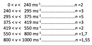
A Russian ballistician, the colonel MAYEVSKI leaned, him also, on the problem and established a table of the exponent of the speed which is constant only for ranges of given speeds.
When the speed increases "n" increases, goes to three, four and then five when we reach the speed of sound. It then decreases sharply. This means that the air resistance reaches a maximum in the vicinity of the speed of sound (transonic speed). It is probably for this reason that the term "sound barrier" was born, inspired by the difficulties encountered by the first supersonic aircraft manufacturers and especially their test pilots.
Below is a table of Mayevski's coefficients.
Figure IV-3-1/2
Note : Some books give n = 2 for v between 50 and 240 m/s. It is traditional to consider that the air resistance is proportional to v (n = 1) for low speeds.
• The retardation
The first experiments whose aim was to define a global equation usable whatever the type of fired bullet ended in failure. It was thus defined a typical bullet whose mass and caliber were taken as a unit for all the calculations, well characterized in terms of its shape, on which the delay R could be put in a simple form :
Equ. IV - 3-1/1
In this formula, R represents the delay expressed in m/s/s, A a function depending on the characteristics of the bullet.
This equation was a good model as soon as one considered that the speed of sound was constant or that its variation had no appreciable incidence on the results of the shots. As we have seen, it was necessary to evolve.
IV-3-2 - TOWARDS A NEW MODEL OF THE SLOWING FORCE
The evolution of weaponry techniques has made it possible to send bullets at increasingly high speeds. It was realized that a single formula of delay could not be used, simply, to account for the braking of the bullet for all the ranges of speeds of which it is animated throughout its trajectory.
Moreover, the high speeds, close to the speed of sound, even supersonic, were not any more the reserved domain of the gunners. The jet propulsion allowed planes to reach these speeds and was going to induce the development of aerodynamics. One realized in particular that the delay or the drag force depended, in reality, not on the speed of the bullet but on the ratio between its speed and that of sound. This ratio is called Mach's number in homage to the physicist who discovered it.
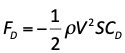
Nowadays, the braking of the bullet is represented by a force, the aerodynamic drag, derived from the Bernoulli's equation:
Equ. IV - 3-2/1
with
Before going further, it is interesting to stop for a moment on this formula.
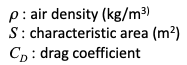
The first member of the equation, the force FDrag entrained is expressed in Newtons. The sign "-" in front of the second member indicates that the force opposes the motion of the bullet, ρ is the density of the air, V the speed of the bullet. We note that it intervenes with the square whatever is the speed of the bullet. Indeed, we are no longer in the application of the Mayevski's coefficients, the exponent must always be 2 at the risk of not being homogeneous to a force. S its apparent surface, CD the drag coefficient, dimensionless. The second member of the equation, expressed thus, has the dimension of a force.
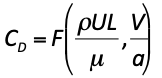
• The drag coefficient CD
The drag coefficient CD is a function of several parameters :
with
In practice, we can neglect the Reynolds' number when the bullet yaw is not impotant. In this case, the drag coefficient depends only on the Mach number, i.e. :
Equ. IV - 3 - 2/2
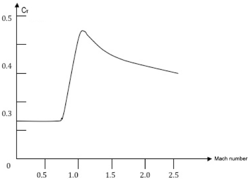
Below is an example of a representative drag coefficient curve for a 7.62 mm Nato bullet.
DRAG COEFFICIENT FOR A 7,62 mm NATO BULLET
Figure IV - 3 - 2/1
It should be noted that it is impossible to represent braking by a single generalized equation. It will be necessary to take into account the variation of CD with the speed. CD thus varies during the flight of the bullet.
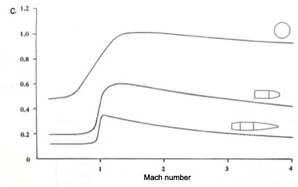
• The drag coefficient varies with the shape of the bullet
The drag coefficient CD varies with the Mach number and the shape of the bullet.
THE DRAG COEFFICIENT VARIES WITH THE SHAPE OF THE BULLET
Figure IV - 3 - 2/2
• The ballistic coefficient and the form factor
1 - The ballistic coefficient
In a classical way, we use the second law of mechanics: F = mdv/dt.
We introduce
with
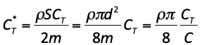
Equ. IV - 3 - 2/3
Note that some works present the ballistic coefficient C as the inverse of that presented above. The mass goes down in the denominator and the diameter squared goes up in the numerator. In this case C is found in the numerator of the formula giving C*T.
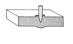
2 - The form factor
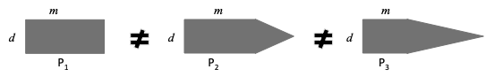
In step 1, we arrived at the result that the ballistic coefficient varies as a function of the mass and diameter or master torque of the bullet. This is an interesting result, but probably not sufficient. What about bullets of the same diameter, of the same mass but of different shape? The image below simply illustrates the question.
Figure IV - 3 - 2/3
The P1, P2et P3 bullets have different air penetration. This seems obvious to the naked eye and wind tunnel tests confirm it. The ballistic coefficient, as presented above, is insufficient ; the shape of the bullet must be taken into account.
We therefore introduce a form factor that we call "i" for the occasion. We thus obtain a more complete and definitive ballistic coefficient.
Equ. IV - 3 - 2/4
To be complete, we must go a little further.
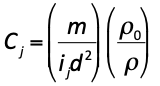
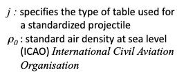
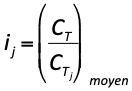
• The generalized ballistic coefficient and the form factor
When we want to describe a phenomenon, we consider all the factors that have an influence on it, even if it means getting rid of some parameters that we may consider as negligible.
The generalized ballistic coefficient :
Figure IV - 3 - 2/4
give
ij is the average ratio of the drag coefficient of a given bullet to that of an experimentally determined normalized bullet.
We have chosen to present a little theory before going into more detail about what happens on the trajectory of the bullet. We are thus better equipped to study the forces to which it is subjected.
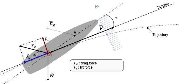
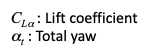
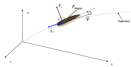
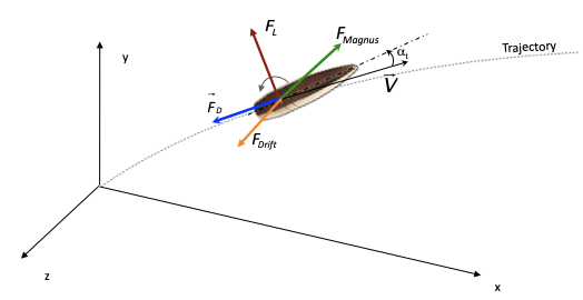
IV-4 - THE FORCES TO WHICH THE BULLET IS SUBJECT
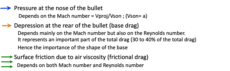
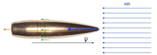
The interaction of the bullet with the air is at the origin of three forces.
Note: generally, the influence of the Reynolds number can be neglected
Figure IV - 4/1
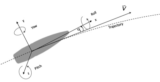
• Yaw - Reference trihedron for the bullet
In practice the bullet is never perfectly aligned with the velocity vector. The angle αt between its axis and the velocity vector is called the obliquity.
Figure IV - 4/2
• Six degrees of freedom
The study of the motions of the bullet leads us to define a reference trihedron on it.
SIX DEGREES OF FREEDOM - REFERENCE TRIHEDRON
Figure IV - 4/3
Note : the direction of the rotations can be reversed according to the books. Modern ballistics merges pitch and yaw into a single term yaw.
• Total yaw αt
The total yaw of the bullet has a horizontal component called the angle of deflection, and a vertical component called the angle of incidence or angle of attack.
SIX DEGREES OF FREEDOM - REFERENCE TRIHEDRON ON TRAJECTORY
Figure IV - 4/4
We introduce δ such that:
TOTAL YAW
Figure IV - 4/5
• Aerodynamic forces and their resultant
By symmetry along the longitudinal axis, the resultant of the aerodynamic forces FR lies on this axis.
There is no symmetry along the transverse axis passing through the center of gravity G. The force FR is at a distance from this point. The forceFR and the weight P create a torque which induces a rotation.
AERODYNAMIC PRESSURE INDUCES TUMBLING PHENOMENON
Figure IV - 4/6
A yaw αt even very small at the exit of the gun produces a force FR itself very small but nevertheless sufficient to increase αt which, in turn will allow an increase in the intensity of FR. A rocking motion is initiated.
•Decomposition of the resultant FR of the aerodynamic forces
We treat FR in two stages.
1 - First step. Reducing FR at the center of gravity
Reducing FR at the center of gravity gives an equipolent force to FR and a rotational moment :
Equ. IV - 4/1
2 - Second time. Decomposition of FR
We decompose FR into two forces: drag FD and lift FL (L for "lift").
DECOMPOSITION OF FR INTO FD and FL
Figure IV - 4/7
• The drag forceFD
The drag force opposes the motion of the bullet and its value is :
It is collinear to the velocity vector V and of opposite direction.
• The lift force FL
he force of lift is perpendicular to the motion of the bullet. On this subject, it may be useful to recall that, on most diagrams, we see the lift directed upwards. These diagrams should be taken as snapshots in which the lift, at that moment, is directed upwards. At another moment, it will be directed in another direction, possibly downwards due to precession. We must therefore be careful not to take an "instantaneous" as a generalization. Only in aeronautics is it ensured that the lift is always directed upwards.
The animation below shows the action of FL according to the angle of obliquity. FL is applied to the center of gravity and thus tends to move it, at each instant, in the direction of its action. Looking at the front of the bullet in the axis of the velocity vector, we would see the center of gravity, if it were under the influence only of FL, describe a circle, projection of a helical motion.
In the animation below, the red circle is the location of the successive positions of the center of gravity (red point). The green circle represents the precession due to yaw. FL is represented by the brown arrow.
Action of FL on the bullet (Move the mouse over the image)
Figure IV - 4/8
Remember that the animation above represents only the action of the FL force. Other forces will be added which will make the motion of the center of gravity more complex.
The value of the lift force is :
with
Equ. IV - 4/7
We find that :
If the axis of the bullet were perfectly aligned with the velocity vector, there would be no lift force. Only drag would exist.
The drawing below shows the instantaneous action of the two forces, drag FD and lift FL.
Figure IV - 4/9
The aerodynamic forces cause the bullet to tilt. It is essential to stabilize it.
In the following chapter, two stabilization methods are presented: stabilization by tail and stabilization by gyroscopic effect. These two methods can be used on small-calibre weapons. The stabilization by tail, because of the presence of the latter, is rather used on sub-calibre bullets. The application of the gyroscopic effect is by far the most common method for stabilizing bullets.
IV-5 - BULLETSSTABILIZATION
• By nature, the bullet is not necessarily stable
ntermediate ballistics has shown us that at the exit of the gun, the gases acting violently on the base of the bullet tend to destabilize it.
When it exits from the barrel, the bullet meets, at high speed, the immobile ambient air. It undergoes a shock which is called, in this case, initial percussion and which also tends to destabilize it.
Moreover, we have seen that, throughout its aerial path, the bullet undergoes a set of interactions with the air whose resultant has, because of the symmetry of revolution, its point of application on the longitudinal axis and in general far from the center of gravity. The result is a couple of forces that apply to make it tip over.
The drawing below shows an unstable bullet by nature.
TUMBLING DUE TO AERODYNAMIC PRESSURE
Figure IV - 5/1
• The stabilization methods
There are several ways to stabilize bullets. We will discuss two of them : stabilization by tailplane and stabilization by gyroscopic effect.
- Fin stabilization
We will treat it quickly, for information. Better than a long speech, the following diagrams describe well the method which consists, with an empennage, in sending the resultant of the aerodynamic forces far behind the center of gravity. The couple of forces thus created tends to maintain the projectile with the point in front.
A projectile equipped with its tail is stable by nature.
FIN STABILIZED PROJECTILE
Figure IV - 5/2
- Stabilization by gyroscopic effect
For many bullets, the stabilization method used is the gyroscopic effect.
The bullet is rotated at high speed (several thousand revolutions per second) along its longitudinal axis. The braking forces of the air, which would cause the bullet to tilt without the rotation, give it a precessional motion at most, provided that the speed of rotation is well chosen. The short duration impulses due to the gas thrust at the exit of the gun and to the initial percussion induce, them, a motion of nutation which is temporarily superimposed on the precession and which is damped relatively quickly.
The bullet being stabilized, it can move according to a trajectory of which one will find a representation below.
Figure IV - 6/1
Description of the scheme
Along the x-axis :Dx is the horizontal projection of D and R. These two projections have the same value since W has no action on the horizontal component. On this axis Dx and Vx decrease when x increases.
Along the y-axis : Ry is the vertical projection of the vector sum of D and W. In the upward phase, D and W contribute to the slowing. In the descending phase D and W act in opposite directions. W tends to accelerate the fall and D to slow it. The direction of R tends to bring the trajectory back towards a vertical until D and W are collinear. The fall speed is constant when D = - W.
From the study of the trajectories of the bullets were born some interesting principles.
• The Saint-Robert's principle
The Saint-Robert's principle is stated as follows: on a family of trajectory with constant initial velocity Vo and initial retardation, the angle of fire α being variable, the points of the same distance OA, OB, OC are characterized by equal values of the lowering (drop) AM, of the duration of the path and of the remaining velocity (see diagram below)
Figure IV - 6/2
The interest of this principle lies in the fact that from a known trajectory, it is possible to calculate others with different angles of fire. The condition being that all other initial values are identical.
• The principle of the rigidity of the trajectory
If we apply the previous principle to a very tense trajectory, the drop is very small compared to the maximum range. The line O1 M1 merges with the line OA . To reach the point M, it will be enough to increase the angle of fire by ε. The trajectory (T2) is obtained by simple rotation of (T1) around the origin 0. Everything happens as if the initial trajectory (T1) was constituted by a rigid wire. Hence the name of the principle of the rigidity of the trajectory (see diagram below).
It should be noted that this principle applies to small angles of site.
Figure IV - 6/3
The consequence of this principle is that if α is the firing angle to hit a target at distance X, the firing angle to hit a target at the same distance on the line of site of (low) inclination s will be a + s by the parallelogram method.
• Alterations of the trajectory
The trajectory of a bullet can be subject to alterations due to its interaction with the air. The consequences are a deviation of the trajectory of the bullet in the horizontal plane which no longer corresponds to the point of impact. The main alterations are :
- The deviation : The deviation : It is due to a side wind which applies to the bullet a force in the same direction thus deviating its trajectory in the horizontal plane. The effect of this side wind is all the more sensitive as the shooting distance is important;
- The Magnus effect : When a rotating body moves in a flow of air, its surface drags the air particles in an asymmetrical way: on one side, the rotation speed of the ball is in the same direction as the air particles and accelerates them, which leads to a decrease in pressure. On the other hand, the rotation speed of the surface is opposite to the air particles and slows them down. In this case, the pressure increases. This pressure difference on the opposite sides results in a force that deflects the ball's trajectory. This effect is well known in soccer, tennis, etc., when you want to give a spin to the ball. In the case of a spin-stabilized bullet with a certain yaw, the Magnus effect deflects its trajectory to the side opposite to its direction of rotation.
The Magnus force is added to the system of forces (see drawing below).
- The drift : Rational mechanics tells us that a body in rotation and in translation tends to align its axis of rotation with the tangent to its trajectory. A bullet stabilized by rotation therefore undergoes, over its entire trajectory, a rotation along its transverse axis of an angle at least equal to twice the firing angle. This tendency to align itself on the tangent to the trajectory means that the bullet "runs after its tangent". It is therefore constantly behind the latter. The combination of the speed of rotation along its transverse axis with the speed of precession, at a given instant, causes a shift of the instantaneous center of precession in the horizontal plane. The bullet is thus presented with a lateral obliquity with respect to the mass of air which it meets. As a result, its trajectory is deviated in the horizontal plane on the side corresponding to its direction of rotation. The diversion is opposed to the Magnus effect and is often called, for this reason, counter Magnus effect. In the case of a shot at short distance or when the trajectory is very tense, with a shooting angle practically zero, there is no drift.
The drift force is added to the system of forces. It is opposite to the Magnus force. For this reason, it is called the counter-drift. (See drawing below).
On its trajectory, the bullet makes its way through the air. This results in remarkable phenomena that deserve to be studied.
• Stability and transonic velocity
The stability of a bullet depends on the resistance of the air. We understand that its passage in transonic speed will disturb it somewhat. In particular when its speed, initially supersonic, decreases with the distance to become subsonic and that, at the same time, its speed of rotation also decreased.
• Subsonic and supersonic bullets. Shock wave, Mach wave. Wake
When the molecules of the ambient air are locally shaken (sound source or other...), this shaking is propagated from close to the neighboring molecules. It propagates at a precise speed, which depends on the characteristics of the medium, called specific speed. It is the speed of sound in this medium, the air in our case (a # 340 m/s).
It should be noted that there is transfer of energy but not of matter.
- Still source
If the source (black point) of the shaking is immobile, the waves generated will be either circular or spherical depending on whether they propagate along two or three spatial dimensions. In all cases, they will be concentric.
During its flight, the tip of the bullet strikes air molecules (this is the reason why it is braked). This shaking will propagate, in the form of circular waves, in all directions and in particular in the direction of the progression of the bullet.
Figure IV - 7/1
- Subsonic velocity
The bullet moves at a velocity lower than the speed of sound (subsonic speed), the sound waves it has generated will move away from it indefinitely and in particular from its tip.
Figure IV - 7/2
- Sonic or transonic velocity
The bullet moves at the speed of sound. The waves emitted by the shaking of the air molecules by its point remain at the level of the latter. The accumulation of these waves locally increases the density of the air and constitutes a kind of barrier that the bullet will have difficulty in crossing.
The front of the bullet will be accompanied by a wave front.
Figure IV - 7/3
- Supersonic velocity
The bullet velocity is greater than the speed of sound. The waves emitted at each moment are overtaken by the tip of the bullet and are left behind. This wave is, at the tip of the bullet, supersonic. It is a shock wave.
At the back of the bullet, the sound waves propagate at the speed of sound and interfere in places. It forms an accumulation of energy on the envelope pressing on the edges of the waves. This envelope has the shape of a cone whose top coincides with the tip of the bullet. This wake is the Mach wave. It is this dry "slam" that we hear that is clearly different from the mouth wave.
Figure IV - 7/4
• Shock wave
A shock wave is a sudden variation of certain physical parameters. An air shock wave is a sudden variation of the pressure followed by a return to normal preceded by a phase of depression.
In an air environment, a pressure wave must meet a certain number of criteria to qualify as a shock wave :
1 - The relative speed of the wave increases with the amplitude of the shock ;
2 - The speed of sound behind the shock wave is always greater than the speed of the wave ;
3 - A shock wave is always subsonic with respect to the medium behind it ;
4 - The shock is always supersonic compared to the environment it meets ;
5 - A shock wave is not an acceleration wave (which propagates at the speed of sound).
We will particularly note characteristic 4, which tells us that for a bullet to create a shock wave, it must have a supersonic speed in the medium in which it moves. The speed of sound in biological tissue is slightly higher than 1500 m/s. This is much higher than the velocity of high velocity bullets such as the .223 Remington (5.56 x 45mm). In the field of lesion ballistics, even these very fast bullets cannot create a shock wave in organic tissue. Therefore, one cannot attribute the observed lesions or part of them to the effect of a shock wave.
The image below represents the umbroscopy of a 7.62 mm bullet moving at a speed of 1.3 Mach.
Figure IV - 7/6
V - TERMINAL BALLISTICS
Terminal ballistics correspond to the phase of interaction between the projectile and the target. To speak of terminal ballistics in the singular certainly does not correspond to reality.
Targets come in all shapes and sizes, so there are many specialties in terminal ballistics.
A projectile is adapted to a target and, for the same type of target, projectiles with totally different principles of action can be used.
• The interaction between projectile and target
The interaction between a projectile and a target is a complex phenomenon, since the results of this interaction are extremely variable depending on the nature of the two protagonists. Hence the need for sorting and classification. The first distinction we propose is between anti-material and anti-personnel ammunition, and we will deal with them in two separate chapters:
The terminal ballistics of anti-material ammunition, and in particular their effect on steel armour. This covers armour-piercing ammunition designed to disable armoured vehicles. Since classifications are necessary, we will consider this field to be that of large-calibre projectiles, i.e. over 20 mm;
The terminal ballistics of ammunition fired by small-calibre weapons (i.e. less than 20 mm) used by infantrymen and certain vehicles. This is called wound ballistics.
Classification is useful, but it doesn't always reflect reality.
Many large-caliber projectiles are not designed to interact directly with a hard target, but to produce an area effect, particularly anti-personnel. Such is the case with explosive shells, which, when detonated, project high-velocity shrapnel from their own casing, or projectiles, of which they are containers, with high anti-personnel power. They can explode on impact (percussion fuse) or at altitude (radio altimeter fuse), depending on the desired effect. Some projectiles contain explosive anti-personnel or anti-tank sub-munitions (Bonus 155 mm shells presented below), which they release at the right moment.
The field of terminal ballistics is vast, and in this short lecture we'll just skim over it, dwelling a little longer on some remarkable projectile/target interaction modes.
• General concepts
Below, we present two important concepts concerning the interaction of the projectile with the target, whatever the nature of the projectile and the target.
- The attitude of the projectile on impact with the target
The effectiveness of a projectile, whether anti-personnel or anti-material, depends on its mode of action, its nature, its constituent parts, its speed, its mass and its attitude at the moment of impact. By attitude, we mean the position in which it is located at the moment of impact on the target. This brings us to the notions of incidence and obliquity, factors which strongly influence the on-target effectiveness of most projectiles, whether intended for anti-material or anti-personnel purposes.
The incidence
If the target is flat, the incidence value is given by the angle defined by the trajectory of the projectile and the normal to the impact plane.
If the target is curved, the angle of incidence is given by the angle between the trajectory of the projectile and the normal to the plane tangent to the point of impact.
The two diagrams below show incidence on a flat target and on a curved target respectively.
Figure V-1 - Incidence on flat target
Figure V-2 - Incidence on curved target
The effects of incidence
An impact occurring at a non-zero angle of incidence produces an effect that varies with the angle of incidence..
Too high an angle of incidence can adversely affect the effectiveness of a shot on armour:
Risk of ricochet and misuse of kinetic energy for projectiles using this mode of action ;
Incorrect engagement, slippage in the case of anti-tank rockets resulting in a detonation fault or malfunction of the shaped charge;
If the ammunition is functioning correctly, the thickness of the armour to be perforated is greater than if the impact took place with a zero angle of incidence, and the effectiveness of the ammunition can be significantly reduced.
The diagram below summarizes the most typical consequences of an impact under various incidence angle.
Figure V-3 - The consequences of the incidence
In the field of personal ballistic protection, a shot fired at a non-zero angle on flexible ballistic protection can place greater stress on the latter than a shot fired at zero angle. That's why standards require tests to be carried out at an angle of incidence, generally 30 degrees.
- Obliquity (pitch and yaw)
Obliquity is the angle between the longitudinal axis of the projectile and its velocity vector. An obliquity is generally favorable to the target, whether it is armour or individual ballistic protection. This is the reason why, during tests on test specimens with small arms, shots are fired at a distance greater than ten meters, generally twelve meters, particularly with long guns. We consider that ten meters from the muzzle of the weapon, the residual obliquity of the projectile is sufficiently low. The ideal is to take, at the moment of impact, high-speed shots in the vertical and horizontal planes in order to verify that the value of the obliquity allows the shot to be accepted.
The two diagrams below show obliquity on a flat target and on a curved target respectively.
Figure V-4 - Obliquity on flat target
Figure V-5 -Obliquity on curved target
The consequences of obliquity
What is true for armour and individual ballistic protection is not necessarily true for the individual, on whom a projectile that is oblique at the moment of impact is likely to topple more easily and thus cause greater injury.
Incidence and obliquity can occur simultaneously. Incidence and obliquity both mean that the projectile's longitudinal axis is not orthogonal to the plane of impact, but they have different effects.
The two diagrams below show the addition of incidence and obliquity, on a flat target and a curved target respectively.
Figure V-6 - Obliquity and incidence
Figure V-7 - Obliquity and incidence
V-I - ANTI-MATERIAL, ANTI-ARMOUR OR ARMOUR-PIERCING AMMUNITION
• Interaction between projectile and target
The interaction between projectile and target is a complex phenomenon that depends on the nature of the two protagonists. It is certainly a matter for the physics of materials, but impact velocities can be extremely variable, requiring the use of models adapted to each range of velocities, or even the creation of new ones. Once again, the need for sorting and classification arises.
• Metal penetration and perforation
There are numerous models for the interaction between projectiles and metal targets. Perforation models have been developed for two of the most common metals: steel and aluminum. The models are not perfect, but we can consider them a good approach. They can even be used for other types of material.
• Velocities classification
Projectiles can strike metal targets at a wide range of velocities. The nature of the target material, steel, is such that interaction modes have to be treated using somewhat different techniques for different velocity ranges. At very low velocities (below 250 m/s), penetration is generally coupled to the overall structural dynamics of the target. In other words, the target responds virtually as a whole. Responses are in the millisecond range. As impact velocity increases (500-2000 m/s), the local behavior of the target material, and sometimes of the indenter, dominates the problem. The action of the indenter becomes increasingly localized in the impact zone. This local zone is about 2 to 3 diameters from the projectile's center of impact. As velocity increases further (2000-3000 m/s), the high pressures involved mean that materials can be modeled as fluids in the early stages of impact.
• Classification of targets
Targets are generally classified according to the material(s) of which they are made and their thickness. The proximal surface is the one impacted, and the distal surface is the one at the other end of the shielding. The distance between the two determines the thickness of the shielding.
Because of the differences in target behavior depending on the distance between proximal and distal surfaces, it is convenient to classify targets into four major groups:
A semi-finite target is one where there is no influence of the distal surface on penetration;
A thick target is one where the boundaries between proximal and distal surfaces influence penetration after the projectile is at a certain penetration distance into the target;
An intermediate thick target is one where the boundaries exert an influence outside the impact;
A thin target is one in which stress or strain gradients are negligible as the projectile passes over it.
• Parameters influencing perforation
The main variables are the properties of the target and penetrator material, the impact velocity, the shape of the projectile (particularly the warhead), the geometry of the target support structure and the dimensions of the projectile and target. With regard to these last points, it should be noted that the standards governing tests on armour materials define precisely, in addition to the characteristics of the projectile, the dimensions of the test specimen and the type of support.
• The different types of interaction between projectile and target
A number of terms are used to characterize the nature of the interaction between the projectile and the target.
- Fracture
Material failure in the form of fracture usually occurs when relatively thin targets are perforated. This failure is due to the initial stress waves, which lead to compression phenomena that the target cannot withstand. This type of phenomenon can be seen in low-density materials (Fig.V-I-I/1). Radial fracture is more typical of brittle targets such as ceramics (Fig. V-I-I/2).
Figure V-I/1
Figure V-I/2
- Spalling & scabbing
Spalling is a material fracture caused by the reflection of the initial compression wave on the opposite side of the plate, the distal surface. It is a common phenomenon under explosive loading, a good example of which is the action of the High Explosive Squash Head (HESH). Spalling is specific to materials with better compressive strength than tensile strength. Scabbing is similar to spalling, but results in the formation of a large plate.
Figure V-I/3
- Plugging
Plugging occurs when a secondary, almost cylindrical projectile of roughly the same diameter as the indenter is created and set in motion by the latter in the material. Failure is due to the shear generated around the moving indenter. Plugging is most likely to be found in all hard plates of moderate thickness. Their presence is more frequent when blunt penetrators are used. They are sensitive to speed and angle of incidence.
Figure V-I/4
- Petalling
Petalization is most often observed on thin plates struck by ogival or conical penetrators at relatively low impact velocities, or by blunt projectiles close to the limit of ballistic resistance. As the bump zone at the rear of the plate is further deformed by the projectile, the elastic properties of the armour are eventually exceeded and a star-shaped crack develops around the penetrator tip. The sectors thus created are then pushed back by the movement of the projectile, forming petals.
Figure V-I/5
Figure V-I/6
- Fragmentation
Fragmentation occurs when the target is composed of brittle, fragile materials. Fragments generated by a destroyed target act as projectiles themselves, and must be considered as penetrators when meeting a subsequent target.
Figure V-I/7
- Ductile failure
Ductile fracture is most frequently observed in thick plates. Perforation occurs through radial expansion of the plate material under the effect of the projectile force.
Figure V-I/8
Figure V-I/9
• Predicting the perforating power of a projectile
Numerous theoretical models have been developed in an attempt to predict the perforating power of a projectile without the need for experimental firing. In most theoretical developments, the volume of the hole produced by the impacting projectile is assumed to be proportional to the kinetic energy lost by the projectile as it penetrates the plate.
V-I-II - ARMOUR-PIERCING AMMUNITION
These are ammunition designed to destroy or disable armoured equipment. Their modes of action are specific to the targets they are designed to hit. Transport vehicles with little or no armour can be destroyed and the personnel on board put out of action by conventional small-caliber weapons, either individual or collective, or by the shrapnel of explosive shells.
Light armoured vehicles, troop transports and armoured reconnaissance vehicles require more powerful ammunition, but their interaction with the target is relatively conventional. It is against heavy tanks that research has been most complex, and has resulted in remarkable armour-piercing effectiveness.
It's always difficult to create classifications, but we can classify armour-piercing ammunition into two broad categories according to the way they work: those that make judicious use of the energy of a high explosive, and those that rely on the hardness and kinetic energy of a projectile.
V-I-II-1 AMMUNITION FOR USE AGAINST LIGHT ARMOUR - SOME EXAMPLES
Against this type of target, we send a projectile combining kinetic energy and hardness. These are usually composite projectiles made of at least two materials. One, sufficiently soft, forms the jacket, enabling the projectile to be fired without prematurely wearing out the gun barrels; the other, often tungsten carbide, supposedly harder than the target, forms the projectile core (Figure V-I-II-1/1) or the warhead (Figure V-I-II-1/2).
Figure V-I-II-1/1 - armour-piercing bullet
The PPI projectile from Société Française de Munitions (SFM) consists of a jacket, soft enough to take the rifling of the barrel, and a hard core which also serves as a warhead, but whose diameter does not allow it to come into contact with the barrel bore (Figure V-I-II-1/2).
Figure V-I-II-1/2 - PPI (SFM) bullet
Together with FIER, we have developed a armour_piercing ammunition called PAR, for projectile with reinforced action, based on a calbre 12 hunting ammunition. The specifications for this ammunition called for good perforating power up to a given distance, and a loss of effectiveness beyond that, in order to limit the risk of colateral effects. The projectile is made up of three parts:
Penetrator ;
A cylindrical hammer that surrounds the penetrator and transmits its momentum on impact;
A lightweight plastic element made up of two parts: a container covering most of the projectile, and a distributor to absorb the gas pressure. This element acts as a sabot, separating from the penetrator and hammer only on impact.
Given the small diameter of the penetrator and hammer, the principle is based on a sub-caliber projectile. The particular use of the sabot-container gives it two roles. The first corresponds to the classic function of a sabot, i.e. to give the sabot-container, hammer and penetrator assembly a much higher speed than that of an all-metal projectile of the same caliber. The second role of the sabot-container is to slow down the projectile on its trajectory, behaving like a container with an anti-aerodynamic profile designed to limit the projectile's effectiveness from a certain distance onwards, in order to limit the risk of a colateral effect. On impact, the shoe-container gradually separates from the penetrator and the hammer by turning back and forth. The hammer transmits its momentum to the smaller-diameter penetrator, thus increasing its penetrating power. If the target is not reached, the projectile as a whole rapidly loses velocity thanks to the anti-aerodynamic profile of the sabot-container.
The ballistic characteristics of this projectile are as follows: velocity at 2.5 m: 490-500 m/s, velocity at 10 m: 440-450 m/s, average kinetic energy at 10 m: 2330 joules, effective range on vehicle and Class 4 ballistic protection: 50 m. The images below show a cross-section of the PAR projectile and its ability to perforate steel plates. Various versions of this projectile have been produced, with powers and performances tailored to users' needs.
Figure V-I-II-1/4 - PAR projectile cross-section
Figure V-I-II-1/5 - Perforating power of the PAR projectile
Projectiles of sufficiently large caliber can be fitted with a number of pyrotechnic elements to give them an explosive and incendiary effect in addition to their piercing power, such as the 12.7x99 mm APEI (armour piercing explosive incendiary) projectile.
Figure V-I-II-1/3 - 12.7x99 mm APEI projectile
V-I-II-2 AMMUNITION FOR USE AGAINST HEAVY ARMOUR
Based on the "spear and armour" principle, the development of anti-tank armour-piercing ammunition has followed that of armour. Among these ammunitions, the most classic are:
Research and development in this field has been prolific. In a lecture, it would be illusory to try to be exhaustive. Instead, we'll review a number of muniton classes and, among these, those we feel deserve particular attention.
V-I-II-3 ARMOUR-PIERCING AND ARMOUR-PIERCING HIGH EXPLOSIVE SHELLS - AP - APHE
• Armour-piercing and armour-piercing high-explosive shells APHE
armour-piercing projectiles are made up of an element capable of piercing armour, the penetrator. The penetrator may be the shell in its entirety, in which case it is traditionally referred to as a cannonball, although its shape is not spherical. If the profile of the penetrator is not very aerodynamic, the front of the shell is made up of an aerodynamic cap that crushes on impact. The very first armour-piercing shells were in fact solid cannonballs. They are now known as armour piercing ammunition, or AP for Armour Piercing.
In later, more sophisticated versions, the piercing element contains a highly phlegmatized explosive initiated, with a delay, by a cap fuse after penetration of the target. This is known as APHE ammunition (Armour Piercing High Explosive).
This type of shell is capable of perforating a tank's armour and exploding inside. It has an anti-personnel effect on the crew and often detonates the ammunition stored inside by sympathetic detonation.
After the Second World War, the development of armour plating made this type of ammunition obsolete.
Figure V-I-II-2/1 shows the schematic diagram of an APHE shell.
Figure V-I-II-2/1 - APHE shell
• High explosive squash head shell - HESH
High Explosive Squash Head (HESH) shells have become obsolete due to their low effectiveness against modern armour. Their mode of operation is nonetheless interesting, as it relies on an anti-personnel effect that can be described as indirect.
These are explosive shells whose warhead contains an inert substance which crushes on impact, delaying initiation of the explosive charge by the rear fuse. The explosion of the shell, when it comes into contact with the armour, causes stress waves in the latter. The first are reflected when they reach the opposite end of the armour, the distal surface, due to the break in mechanical impedance. On their return, they interfere with those coming from the outer surface. This complex system of stress waves causes fragmentation of the inner surface of the armour, and an anti-personnel effect, even without perforation.
Figure V-I-II-2/2 - HESH shell
Figure V-I-II-2/2 - HESH shell effects
V-I-II-4 SHAPED CHARGE SHELLS
These shells contain an explosive charge configured so that, on impact, the energy of the explosion is focused on a very small area of the armour to increase perforating power. These charges are known as shaped charges. We'd like to take a moment to explain how they work.
• History of shaped charge
As in many fields of science, the discovery of the shaped-charge effect is much debated and disputed. Although the English attribute it to DAVY (1778-1829) and it is often referred to as the "MUNROE effect" or the "NEUMANN effect", it seems that the first known published document is by Max von FORSTER.
The brochure appeared in Berlin in 1883 in Dingler's Polytechnisches Journal under the title "Versuch über geprefster Schiefsbaumwolle (Research into Compressed Cotton-Powder)". It seems, however, that the philosopher-theologian and mystic Franz Xaver von BAADER, holder of an engineering diploma from the Freiberg School of Mines, proposed the use of dome-shaped explosive charges in geological exploration before 1790.
Nevertheless, the name most often associated with the discovery of the shaped charge effect is that of Charles E. MONROE. In an experiment, MONROE observed that when an explosive charge was detonated while the face bearing the indented inscriptions was in contact with a metal plate, these inscriptions were mirrored on the plate. This was all it took to continue the tests. He found that when the face of the explosive charge in contact with the metal had a cavity, a cavity was also observed on the metal after detonation. He also found that if the charge was moved further away, the cavity became deeper, until this effect disappeared beyond a certain distance. This behavior was quite different from that observed with an explosive charge whose flat face was in contact with the test tube. In this case, the effect of the explosion diminished with distance.
Summary of shaped-charge characteristics
The face of the charge in contact with the test piece is flat. After detonation, hammering is more or less pronounced, depending on the power of the explosive charge;
The face of the charge in contact with the test piece has a cavity. After the charge has exploded, a crater is formed in the metal;
The face of the charge in contact with the test piece has the same cavity as in A, but the cavity face has been covered with a layer of metal. After detonation, the cavity produced in the metal is deeper than in B ;
The charge is no longer in contact with the test piece but has been moved away. The detonation produced a deeper and narrower crater than in C.
The figure below summarizes the observed phenomenon.
Figure V-I-II-4/1 -Shaped charge effect
Since then, numerous studies have been carried out and several theories have been proposed to model what was observed during the experiments.
• The principle of shaped charge
A shaped charge is an explosive charge designed in such a way that it has a cavity facing the target. During detonation, a cavity is produced in the target material.
At the time, in the absence of any means of visualizing such a rapid phenomenon, the best explanation found was a focusing of the explosion's energy. When the detonation wave reaches the top of the cavity, the gases come together to form a high-density, high-velocity jet with a long-range effect.
Almost by chance, a researcher, who had covered the face of the cavity with metal in order to avoid an explosive loss, noticed an increase in the depth of the cavity on the specimen. In addition to the effect of gases, the coating material of the load cavity seemed to behave itself like a dart.
This brings us to the basic shaped charge diagram shown in the figure below.
Figure V-I-II-4/2 - Shaped charges with conical and hemispherical cavities
• Jet formation. The example of a lined conical cavity
We've chosen to use a conical cavity as an example, as it's very common. We can extrapolate this example to other cavity shapes, bearing in mind that the results on target may differ, particularly in terms of crater diameter and depth.
When the detonation wave reaches the top of the cone, the jet begins to form by turning over the coating material. When the reversal is complete, the material forms a viscoplastic jet. Observations show that there is a velocity gradient between the head of the jet, which can reach a velocity of around 10,000 m/s, and the tail, which has a velocity of around 2,000 to 3,000 m/s. This velocity gradient causes the jet to stretch, which can lead to its rupture and fragmentation, which must be avoided. Indeed, the penetration power of this jet is, among other parameters, proportional to its length. It is therefore necessary to use a highly ductile material for the cavity lining, i.e. one capable of undergoing considerable stretching before breaking.
The figure below shows a schematic diagram of jet formation.
Figure V-I-II-4/3
• Ductility of the cavity lining material
Ductility is the ability of a material to undergo plastic, i.e. irreversible, deformation before breaking. This is the factor to look for in the liner. It is an essential factor, since there is a velocity gradient in the jet between the head and the tail, and the jet's penetration power is proportional, for a given mass, to its length.
Numerous studies have been carried out to find the most suitable liner material. However, factors other than ductility need to be taken into account, in particular high density and high sound velocity in the material, the latter property having an influence on the velocity of the jet head, and therefore on perforating power.
The most ductile material is gold. One gram of gold can produce a wire 2000 meters long. Tests have been carried out with gold and with other materials offering other advantages. These include molybdenum, tungsten, copper, tantalum and depleted uranium for its high density. We have also seen for ourselves the effectiveness of glass for cylindrical loads and industrial steel for cutting loads. In some tandem charges, nylon, as a liner for the front charge, has been successfully tested by increasing, compared to copper, the diameter of the crater in which the jet action of the rear charge could be exerted. As for gold, although tests have been carried out with it, it does not appear, for fairly obvious reasons, that military charges are made with this metal.
• Interaction between shaped charge and armour
The perforation of armour by projectiles launched by conventional firearms, i.e. with a velocity generally less than 1000 m/s, constitutes a plastic deformation which comes under the heading of solid mechanics. To achieve this perforation, a projectile made from a very hard material is fired at a target made from a more malleable material.
We can see that, as we increase the impact velocity of a projectile, we enter an intermediate phase between solid and fluid dynamics. The boundary is not clear-cut, but we tend to give a speed of around 1200 m/s as a reasonable frontier. Among the researchers who have worked on this subject is Hermann GERLICH, who, thanks to the development of a special cannon, was able to launch 70 mm-calibre anti-tank projectiles at speeds of the order of 1,800 m/s. Subsequent observations established that, at these velocities and beyond, the importance of projectile hardness faded in favor of projectile speed, and that a projectile made of soft material could penetrate hard armour provided it went fast enough.
In the case of shaped charges, given the speed of the tip of the jet, we could consider that we were in the midst of fluid dynamics. In reality, however, the strict application of the equations of fluid mechanics does not adequately reflect the observations for the whole phenomenon. It is therefore necessary to modify them somewhat.
Parameters affecting shaped charge efficiency
A number of parameters determine the efficiency of a shaped charge. These include
Explosive: the explosive with the highest transformation speed delivers the best performance;
Charge length : to obtain the desired effect, you need the right amount of energy, i.e. the right amount of explosive. In addition, the height of the head, i.e. the distance between the initiation system and the top of the cavity, must ensure that the detonation wave is as homogeneous and flat as possible;
Charge containment : the thickness and geometry of the confinement are decisive in order to obtain a detonation pressure and propagation of the detonation wave that are adequate, flat and homogeneous;
Initiation system : it must be positioned at the back and at a specific distance from the top of the cavity. Initiation can be performed at a single point or at several;
Cavity shape : the conical shape is the most commonly used. There are also trumpet-shaped cavities, with shapes varying along their length. In the case of conical cavities, the value of the angle at the apex has an influence on the shape of the jet and therefore on the diameter and depth of the crater obtained on the target, see figure V-I-II-4/4 below. The angle is adapted to the desired effect. The distance between the base of the cavity and the target is decisive, as it must allow the jet to form while avoiding its fragmentation;
Type and thickness of cavity liner : the material is chosen according to its ductility and density. The overall velocity of sound in the material must also be taken into account, with studies by Carleone and Chou establishing in a 1981 BRL report that the speed of the tip of the jet is 2.41 times the speed of sound in the material. Manufacturing methods are also important. Two-material liners have been used.
A shaped charge is therefore a high-tech system. However, it should be noted that tests on improvised or "makeshift" charges in which we took part showed that very good shaped charge effects could be obtained while overcoming a certain number of the parameters described above. Admittedly, the results obtained were probably inferior to those that could have been achieved with the same quantity of explosive packaged in an industrially manufactured charge, but the results were highly satisfactory.
The "shaped charge effect" enables action at a distance of the order of a few diameters from the charge, depending on the desired effect. The question naturally arises as to whether it would be possible to obtain a similar effect at a longer distance. The answer is yes, and this possibility is offered by so-called "flat" charges.
The figure below shows the variation in jet shape as a function of the angle at the top of the conical cavity.
Figure V-I-II-4/4 - Jet shape as a function of
cavity apex angle - W.P. WALTERS & A. ZUKAS
• Going further with flat charges
With flat charges, we enter the realm of core-generating charges or explosively formed projectiles (EFPs).
The principle of flat charges is quite similar to that of shaped charges, except that the cavity has been replaced by a metal disk, generally made of copper. The explosive charge is configured and initiated in such a way as to produce a flat detonation wave, moving perpendicularly from front to back, and enabling the disc to be sent at very high speed, of the order of 2,000 to 2,500 meters per second, and obtain an anti-tank effect a few dozen meters away. The concept of the horizontal-action anti-tank mine was born. Note that the words "horizontal action" should not be taken literally. In fact, anti-tank shell sub-munitions and certain anti-tank missiles have a more vertical action at a distance.
However, the term "flat charge" is not really appropriate. The disc is stamped in such a way that it has one concave and one convex side, like a plate, as it was often called. This plate is placed at the front of the charge so that the concave side faces the target.
The figure below shows a flat charge diagram.
Figure V-I-II-4/5 - Flat charge diagram
Flat charges with surprising effects
Pierre DEFRANCE, Ingénieur Militaire en Chef de 1ère Classe, speaking at a conference in 1951, expressed the astonishment of experimenters at the discovery of the effect of flat charges:
« The effect of the flat charge, acting at a great distance from its point of detonation, appeared to those who witnessed it to be even more astonishing than that of shaped charges. The fact that a static mine could pierce an armoured steel plate several centimetres thick at a distance of a hundred metres, and that the experimenter could even aim at the plate, which was nevertheless small, and hit it, overturned many ideas about the use of explosives. »
This quote says it all.
• Towards a better understanding of the phenomenon
At the end of the 1940s and the beginning of the following decade, high-speed visualization methods for observing the phenomenon, and in particular the moment of impact, were not sufficiently developed. It was generally sufficient to observe the result on target and, from there, to interpret, if not imagine, the whole phenomenon. Early reports tended to show that the disc was propelled without noticeable deformation, and hit the target in its virtually initial state.
This idea stemmed from the fact that the shielding had a hole of a diameter very close to that of the disc. We now know that, in certain experimental configurations, the disc is deformed and the edges are turned forwards like the letter W.
The figure below shows the deformation phases of the disc during flight.
Figure V-I-II-4/6 - Disc deformation during flight W formation (Hallquist 1980)
• Core-generating charges - Explosively formed projectiles
They are also known as self-forming projectiles and EFPs (Explosively Formed Pojectlles).
Today, numerical simulation combined with high-speed imaging enables us to master the phenomenon in detail, from the moment of detonation to the moment of impact on the target. We now know that, for certain configurations of the disc, it deforms to form a penetrator. What's more, modern computer technology makes it possible to run simulations, saving time and money. See the two figures below.
The detonation of the charge, through interaction with the metal disc, creates a penetrator with a high initial velocity (Vo ≈ 2000 to 2500 m/s), which is capable of perforating armour several tens of metres away. But this is far from the end of the story. Problems naturally arise. These mainly concern the loss of metal disc material and the need to improve precision.
Prevent disc to scabbing
When the detonation wave reaches the disc, it causes mechanical stresses within the material, leading to spalling or scabbing of the front face. This phenomenon causes a loss of mass. The penetrator's kinetic energy is reduced, while its perforating power depends directly on it.
One solution to this problem is to add a second, lower-density disc at the front. Although overall energy efficiency is reduced by the presence of the front disc, this loss is largely offset by the conservation of the rear disc's mass and therefore its kinetic energy. This method was developed in France by GIAT (now NEXTER).
Improving penetrator aerodynamics
The detonation of the charge creates an approximately rod-shaped core, with an aspect ratio of between 3 and 5 and a high muzzle velocity (V0 ≈ 2000 to 2500 m/s). To remain fully effective, this core must possess aerodynamic qualities that enable it to remain stable on its trajectory and hit the target with precision.
We therefore sought to provide this core with a skirted rear stabilizing zone. This skirting was made possible by thinning the edges of the disc. However, this skirting generally presents an irregular profile that can impair precision.
Methods have been developed, notably in the USA, to create a symmetrical skirt forming a tailfin. To achieve this, the metal disk has to be machined very precisely, creating zones of reduced thickness which, when the detonation wave arrives, produce folds which then form fins. This method requires a complex and costly manufacturing process.
In France, a less complex method has been sought by placing inserts in the charge. These inserts are arranged in such a way that the detonation wave propagating between them and the liner is no longer a surface of revolution, but has a rotationally symmetrical pressure distribution around the axis of the charge. During detonation, this device bends the liner in such a way as to create a kind of skirt fitted with stabilizing fins (GIAT patent).
The image below shows an example of the formation of a symmetrical "jupage".
Figure V-I-II-4/8 - Formation of the penetrator "jupage" - Simulation
Research into shaped charge and then flat charge effects has led to the development of devices capable of perforating armour at distances ranging from a few centimetres to several tens of metres, such as horizontally-acting anti-tank mines.
The integration of EFP in high technology
Today, EFPs are used by modern technologies such as the BONUS shells developed by NEXTER in France and Bofors in Sweden, or the Swedish N LAW anti-tank missiles designed by Saab Bofors Dynamics and manufactured by Thales Air Defence.
Technological advances have made it possible to use container shells to send a core-generating charge several tens of kilometers away. Controlled by sophisticated electronics, it is capable of selecting a moving target and destroying it. We're talking about the 155 mm BONUS shell carrying two core-generating charges, manufactured by NEXTER in France and Bofors in Sweden. The following is a summary of the characteristics of this ammunition and its effectiveness in the field (sources: NEXTER and BAE Systems).
Figure V-I-II-4/9 - Warhead characteristics
Figure V-I-II-4/10 - The BONUS shell and its two submunitions
BONUS shell submunition destroys a tank
Now that the shaped charge and flat charge effects have been presented, let's go back to shaped charge shells.
To reach armoured vehicles at great distances, we need to return to conventional firearms, which are the only way to deliver these special charges to the target.
• Going even further with shells
Once the effectiveness of shaped charges had been demonstrated, and the parameters influencing their performance defined, all that remained to be done was to find a way of sending them remotely onto the armour.
The 1940s saw the development of shaped charge magnetic grenades, such as the German "Hafthohlladung 3 and 3.5", which the infantryman had to place on the tank. In 1941, France introduced the first shaped charge anti-tank rifle grenade. Anti-tank rocket launchers made it possible to increase the range of fire, but the shell remained the best means of achieving long firing distances. During their development, a major difficulty arose.
• The shaped charge problem in gyrostabilized shells and the solution: the G shell
This problem became apparent as soon as we set out to create shaped charge shells. The operating mode of shaped charges and the gyrostabilization of shells proved incompatible. In France, this problem was solved in a remarkable way.
In his book on large-calibre armaments, Michel TAUZIN, Chief Armaments Engineer, reports that in 1945, shaped charges mounted in gyroscopically-stabilized artillery projectiles fired by rifled guns were found to be much less effective than short-range anti-tank infantry rockets, which were stabilized by a tail. But we didn't know why.
This problem was studied at the LRSL (Laboratoire de recherches de Saint-Louis) by Professor SCHARDIN and his team of German staff, who had agreed to come to France with their laboratory equipment at the end of the Second World War.
For information, the Laboratoire de recherches de Saint-Louis (LRSL), which later became the Institut franco-allemand de recherches de Saint-Louis (ISL), was officially created in 1958, bringing together German and French researchers in the field of armaments. On the German side, the forerunners were Professor Hubert SCHARDIN, a scientist and ballistics expert, and his team, as early as May 1945, at France's suggestion. They were installed in industrial premises in Saint-Louis in the Haut-Rhin region, a commune close to the German border. Initially considered an "Annexe du Laboratoire Central de l'Armement" laboratory, under the direction of Chef d'Escadron CASSAGNOU, the center became the "Laboratoire de Recherches de Saint-Louis" (LRSL). This institute, which we have had the pleasure of frequenting, has always been at the forefront of research in scientific fields relating to armaments. Let's close this parenthesis and move on to the problems of shaped charge jet cohesion.
• Disaggregation of the rotating shaped charge jet
Examination of a shaped charge jet in flight, using the X-ray flash method developed by Professor Schardin, will provide the key to the problem: the centrifugal force generated by the projectile's rotation breaks up the jet and disperses it. The loss of piercing power is noticeable at rotation speeds of around 20 to 25 revolutions per second, whereas the rotation speeds required to stabilize shells are several hundred revolutions per second.
This leads to the conclusion that a shaped charge mounted in a gyro-stabilized projectile can only be effective if it is independent of the shell's outer body.
The study of a projectile concept satisfying this condition was undertaken in Saint-Louis by a German engineer named Gessner, hence the name G shell given to this variety of projectile. The general principle is simple in its statement, but the practical realization is difficult because the inner part of the projectile containing the shaped charge cannot be totally independent of the outer body. It will be to LRSL's credit that it has found a solution to ensure that the friction between the outer and inner shells does not cause the shaped charge to rotate faster than 20/25 revolutions per second on impact.
This research led to the development of a shaped charge, gyro-stabilized artillery projectile with a perforating power at any distance of around four times the calibre of the shaped charge. In 1955, the 105 mm G shell, designed for the AMX 13 tank, was fired for the first time at a muzzle velocity of 800 m/s. The operational validity of the gun-ammunition pairing was confirmed:
Dispersion on the order of 1/1000 at 1,000 m and 1.3/1000 at 1,400 m ;
Four-calibre shaped charge perforation, i.e. this projectile is guaranteed to pierce 180 mm of armour at any distance, at 60° incidence.
To achieve this performance, a clever system had to be devised so that shaped charge and gyrostabilization could coexist.
• A shaped charge shell mounted on ball bearings
That's often how this shell is presented to us. It's partly true. But at the start of the shot, the acceleration undergone by the assembly tends to increase friction between the inner part containing the shaped charge and the rotating outer body. The latter tends to drag the shaped charge into its rotation. It was therefore necessary to add a device to the ball-bearings connection system, enabling the inner and outer parts to be separated as much as possible. This device, whose vital importance is generally masked by the original and more comprehensible principle of ball bearings, consists in the ulization of propellant gases via vents. These compensate for the inertia of the inner part, which tends to increase friction.
The figure below shows the overall layout of the G shell. We've marked in red the elements (ball-bearings and gas inlet and outlet vents) that minimize forttements between the inner part containing the shaped charge and the outer part.
Figure V-I-II-4/11 - Schéma de l'obus "G". In red: ball-bearings and gas inlet and outlet vents
Chief Armaments Engineer TAUZIN briefly explains the principle:
An external body carrying the belt is driven in longitudinal acceleration and rotation (of the order of 300 revolutions per second), giving it the rotational energy required to stabilize the assembly;
An inner body carrying the shaped charge is supported by ball-bearings on bearings forming part of the outer body. In this way, the inner body is not rotated, or is rotated only a few revolutions per second, and retains its perforating capacity.
It's easy to understand the many obstacles that had to be overcome to ensure dissociation between the inner part of the shell containing the shaped charge and the rotating outer body, during all phases of firing. These obstacles mainly concerned two aspects of the project:
Mechanical operation to ensure virtually zero rotation of the inner body. The key to achieving this is the provision of vents in the base of the outer body for the admission of powder gases, which push the inner body forwards and thus prevent it from rotating as a result of friction;
Pyrotechnic operation, requiring almost instantaneous operation (less than 30 microseconds) between impact and detonation of the shaped charge - a feat never before achieved, and which led to the development of a completely new piezoelectric rocket. This charge initiation time had to be compatible with a suitable action distance, to enable the shaped charge jet to form properly, despite the high impact velocity.
Qualities and weaknesses of the G shell
The G shell was adopted in 1961 as the OCC 105 F1. While its qualities were undeniable, there were also a number of weaknesses.
The qualities
Very high perforation capacity. The 105 mm "G" shell regularly perforates the 152 mm NATO test plate at 64°20' at all distances and with a significant rear effect;
Very good accuracy: H+L routinely below one thousandth at all firing distances. This accuracy was probably due to the fact that all parts were machined, so there was virtually no imbalance. Reliable muzzle pressure also contributed to firing accuracy.
Weaknesses
The muzzle velocity (V0), and therefore the combat effective range, is low compared with the muzzle velocities of kinetic energy shells, particularly sub-caliber shells, which can be used on the same vehicles.
On the AMX 13 tank :
- V0 with 105 G: 800 m/s ;
- V0 with 75 mm armour-piercing: 1000 m/s ;
- V0 with 75/54/40 sub-caliber: 1310 m/s.
On medium tanks such as AMX 30, Leopard 1 or Centurion :
- V0 with 105 G : 1000 m/s ;
- V0 with the English sub-caliber : 1475 m/s ;
Even if the G shell's excellent accuracy somewhat masks its low muzzle velocity, and therefore its useful combat range, the fact remains that serious competitors, both in terms of ballistics and industrial production, were pointing their warheads at it. Sub-caliber shells undeniably showed their superiority.
In ballistic terms, the reason for their superiority is unstoppable. The probability of hitting a fixed target is linked to dispersion, which in turn depends on the useful combat range - that is, in meters, slightly more than the initial velocity V0 in meters per second - and therefore ultimately on initial velocity. And the muzzle velocity of sub-caliber shells is much higher than that of shaped charge shells.
A parametric study of the effectiveness of the AMX 13 tank armed with either the "G" shell (V0 = 800m/s) or the sub-caliber shell (V0 = 1310 m/s) showed the sub-caliber to be unquestionably superior.
The only criticism that can be made of the G shell is that France was proud to have produced such a complex projectile, in both its mechanical and pyrotechnical aspects, which would remain without equal anywhere in the world. For a time, the G shell overshadowed the work that France was nevertheless doing on sub-calibre ammunition.
However, it should not be imagined that France was stubbornly sticking to shaped charge shells for no rational reason, regardless of how they were stabilized. These ammunitions were, in fact, capable of excellent perforating capacities, while at the same time imposing a linear momentum acceptable to light armoured vehicles at the start of the shot, notably the 90 mm caliber light vehicule-machine gun (AML 90), which was a great success in the export market.
However, the other major NATO nations (USA, Great Britain, Germany) chose the British 105L7A1 gun and its sub-caliber ADPS (armour Piercing Discarding Sabot) ammunition.
The performance of sub-caliber shells was obvious, but shaped charge shells had not said their last word. Especially if gyroscopic stabilization was replaced by tail stabilization.
• Tail-stabilized shaped charge shells
The solution proposed by the G shell was elegant and effective, but its industrialization was complicated. It was necessary to consider a simpler method of ensuring the projectile's stability on its trajectory. We therefore turned our attention to another well-known stabilization method: the empennage or tail-stabilization. The study proved complex, however, as the only known empenned projectiles were anti-tank rocket launchers and mortars, all of which were subsonic. The field of supersonic empenned projectiles had to be explored.
It's not easy to focus, but the principle is. There are two systems. Either the shell is fitted with a tail unit that deploys as it leaves the gun. This is the case, for example, with the Russian shell shown in the image below, Figures V-I-II-4/12 and V-I-II-4/12-bis. Or the tail is calibrated, as on the French Model 62 shell, also shown below, Figure V-I-II-4/10.
It should be noted that the French engineers, perfectionists, had decided that, to optimise precision, a slight rotation of a few revolutions per second was necessary in order to reduce the shell's misalignment and enable it to maintain its theoretical trajectory.
V-I-II-5 KINETIC ENERGY SHELLS
We know that when the impact velocity of a projectile is increased, the interaction between the projectile and the target corresponds to an intermediate phase between solid and fluid dynamics. We mentioned above the work of Hermann GERLICH who, thanks to the development of a special gun, was able to launch 70 mm calibre projectiles, intended for anti-tank warfare, at speeds of the order of 1800 m/s.
To achieve this speed range, we use the principle of sub-caliber projectiles.
• Sub-caliber shells
These shells fall into the category of sub-caliber shells with a discarding sabot or, in other words, APDS (Armour Piercing Discarding Sabot).
One way of increasing the speed of a projectile, for the same caliber and the same pressure in the barrel, is to reduce its mass. The idea is therefore to replace the perforating bullet with a smaller-caliber perforating element, possibly of the same density, inserted in a sabot made of a lightweight material. As the perforating element and the sabot are of lower mass, their initial velocity is higher than that of the bullet. On exiting the barrel, the sabot, under the action of gases and centrifugal force, separates into several elements of the penetrator, which continues its trajectory towards the target, reaching it at a higher velocity than the cannonball would have done, thus enhancing penetration. The penetrator is stabilized by the gyroscopic effect. The speed of rotation ensuring its stability on its trajectory is communicated to it, at the start of the shot, by the sabot. In terms of performance, the reduction in caliber results in lower aerodynamic drag and higher surface energy density on impact. The loss of mass due to the reduction in caliber is largely offset by the increase in speed, which is squared in the expression of kinetic energy. Depending on its value, this increased velocity can modify the nature of the interaction between the penetrator and the target, favouring penetration.
Below are a few examples of APDS projectiles. Note the conical contact between the sabot and the base of the sub-caliber projectile, which encourages the latter to rotate during acceleration in the barrel.
Figure V-I-II-5/1 - British 105 mm APDS shell
Figure V-I-II-5/2 - Australian 20 Pdr APDS MK 3 shell
Figure V-I-II-5/3 - French 75 mm APDS shell
Sub-caliber armour-piercing shells had proved their superiority over shaped charge shells. As a result, they were adopted by all armies. But the best never stays the best for long. Developments in armour, and in particular the adoption of reactive armour, were to change the situation once again.
• Armour evolution and response
Research into the metals and metal alloys used in the design of armour is making it increasingly resistant. In addition, the use of reactive armour, consisting of multiple cassettes placed in front of conventional armour, is leading to the obsolescence of conventional armour-piercing shells. This is because the reactive armour cassette, composed of a layer of explosive placed between two metal plates, detonates on impact. The outer plate is projected in the direction of the penetrator, which is then faced with an increased thickness to penetrate, causing premature erosion or even dislocation.
Anglo-Saxon advantage
In response to the increasing armour performance, Anglo-Saxons are ahead of the game. They have been using a gyroscopically-stabilized sub-caliber shell for some time (Figure V-I-II-5/1), and will be the first to undertake a large-scale study of a highly innovative sub-caliber, the arrow projectile. This represents a real technological leap forward, considerably increasing both the probability of hit and the probability of destruction.
As early as the 1960s, the Russians were using such a projectile for the T62 tank, ahead of the Americans, whose M735 projectile was the first arrow projectile in the Western camp.
The French are well aware of the existence of such developments. In fact, the LRSL (then ISL) employed a number of former staff from Peenemünde, where arrow projectile studies had been carried out during the Second World War; but this line of research was practically abandoned until 1964.
The emergence of heavy tanks capable of withstanding the amount of movement generated by the firing of an arrow shell was to encourage the development and adoption of the arrow shell.
• The arrow shell
Like other sub-caliber shells, the APFSDS (Armour Piercing Fin Stabilised Discarding Sabot) is a projectile whose effectiveness on armour is due solely to its kinetic energy.
Operating principle
While the development of this type of ammunition is complex, the operating principle is relatively simple to understand. A projectile is fired at a target or armour, and will only act through its kinetic energy. Since a projectile's kinetic energy depends on its mass and the square of its velocity, the ideal is a very dense projectile, of very small calibre to obtain the greatest surface energy density, driven by a very high velocity (at least 1500 m/s).
This led to the idea of sending a cylindrical rod of very small caliber and very high elongation (15 at least), with a tapered tip, made of a very dense material (tungsten alloy or depleted uranium) to optimize perforation capacity.
It's the penetrator's density, elongation and velocity that count, not its mechanical characteristics. This makes the penetrator much easier to manufacture than was the unmachinable tungsten carbide core of the classic sub-caliber. Such an elongated projectile can only be aerodynamically stabilized to resemble an arrow. Abandoning gyroscopic stabilization, the arrow shell is fired from a smoothbore barrel. However, to ensure a certain degree of compatibility, specially-configured sabots allow the shell to be fired into rifled barrels.
To reach the required speed, we use the principle of sub-caliber ammunition. In this case, the rod is encased in a larger-diameter sabot made of lightweight material. The role of this sabot is to absorb most of the gas pressure, which generates a significant propulsion force on a sabot and rod assembly that is relatively light for the caliber of the gun. The figure below shows an arrow shell.
Figure V-I-II-5/4 - French 105 mm F1 OFL 105 arrow shell
The arrow shell principle achieves muzzle velocities of between 1,500 and 1,800 m/s, depending on the weight of the shell. Once the shell has exited the barrel, the gases cause the sabot components to separate. The rod, stabilized by a tail, continues its trajectory towards the target.
Under these conditions, the armour perforation mechanism is very different from that of a conventional perforating gun. The armour is no longer sheared, but penetrated "hydrodynamically". The term "hydrodynamic" is used in quotation marks because, as with shaped charges, the equations of fluid dynamics do not fully account for the whole phenomenon. The penetrator acts like a jet of shaped charge, consumed as it penetrates.
Among the materials used to optimize perforation capacity are tungsten in the form of carbide or other alloys, and depleted uranium. Contrary to what some information warfare propaganda suggests, depleted uranium is not used for its supposed radioactive properties. Its use is mainly due to its density, which is close to that of tungsten, its relatively low cost and its pyrophoric effect, which consists in the fact that particles of this metal, produced when interacting with armour, ignite spontaneously, thus adding an incendiary effect to the perforating one.
Evolution of the arrow shell
In France, the initial delay was made up. In 1975, the development of the arrow shell by EFAB (Etablissement de Fabrication d'Armement de Bourges) was practically complete. It earned Chief Engineer Moreau and Principal Engineer Sauvestre the Chanson prize in 1979.
The first tests involved a relatively short bar, literally pushed by a sabot. Stability problems were encountered. To overcome this, the action of the sabot on the jib had to be exerted well ahead of the center of gravity. The result is the push-pull arrow principle, which achieves a standard deviation of 0.2/1000 m in both height and direction, and guarantees a very good probability of hitting the target on the first try up to at least 2,000 m. The figure below summarizes the development of the arrow shell in France.
Figure V-I-II-5/5 - From left to right : Evolution of French arrow shell
The first application will involve upgrading the armament of the AMX-30 B2, which will receive the OFL 105 Mle F1 projectile.
From the outset, the Leclerc tank will benefit from the OFL 120 F1 A, an arrow-shaped ammunition with exceptional performance:
Initial velocity : 1 790 m/s ;
Effective range : 4 000 mètres ;
Perforation of homogeneous and composite targets on heavy tanks and reactive targets.
Nexter Munitions' latest improvements to this ammunition give the 120 SHARD anti-tank shell, in series production since the end of 2022, increased perforating power combined with very high precision.
SHARD, an acronym for "Solution for Hardenered ARmour Defeat", is the most powerful tungsten alloy APFSDS currently available. Its penetration capabilities are almost 20% higher than those of commercially available ammunitions. It combines an unmatched level of penetration against metal armour and complex targets with a very good level of dispersion. Its innovative architecture, combining an extended penetrator, an optimised sabot and a low-erosive propellant powder, enables it to generate superior energy while significantly reducing the pressure level, thus lessening significantly the tube wear. SHARD, developed in an agile mode, has been designed to allow incremental upgrades in order to adapt to future threats, including the incorporation of new penetrator technology and higher energy powders. Thus, in a short time, the terminal ballistic performance of the ammunition can be increased by more than 20%.
Figure V-I-II-5/6 - Obus flèche SHARD
Figure V-I-II-5/7 - Obus flèche SHARD. Séparation des éléments du sabot
Documentation NEXTER
V-II - WOUND BALLISTICS
Wound ballistics is the study of the interaction between a projectile and living tissue. Systematic analysis of lesions has enabled us to identify a lesion pattern: the lesion profile.
• The concept of wound profile
Introduced by M. FACKLER and J. BRETAU, the wound profile, illustrated below, describes the interaction between the bullet and the target.
Figure V-II / 1
A : Proximal path (Neck)
B : Tumbling or mushrooming area
C : Distal path
• The three main modes of action of a bullet
Overall, when a bullet interacts with a target, it can exhibit three kinds of behavior :
1 - Tilting or overturning ;
2 - Expansion ;
3 - Fragmentation ;
Below is a drawing showing these three modes of action.
Figure V-II / 2
The graphs below are the results of experiments. They illustrate the correlation between the attitude of the bullet in target, its deceleration and the importance of the wounds.
Figure V-II / 3
• Different bullets, different effects
The bullets are given different shapes and structures depending on the desired effect on the target.
DIFFERENT BULLETS : DIFFERENT EFFECTS
Figure V-II / 4
* The bullets above are not to scale.
• Tests - Reference materials
Experimentally, one method for studying the lesion potential of bullets consists of firing on reference materials (gelatin, ballistic gels), somewhat improperly called "simulants".
Analyses of feedback from the field concerning the lesionary effects of bullets, associated with the study of their behaviour on "simulants", make it possible to generate transfer matrices allowing the extrapolation of observations on "simulants" to the lesionary effects likely to be observed on living tissue.
Below are two examples of shooting on gelatin blocks.
Jean-Jacques DÖRRZAPF
Former head of the Wound Ballistics Unit
at the Technical Center for Internal Security
Expert at the International Criminal Court
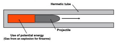
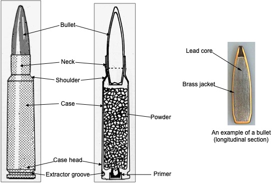
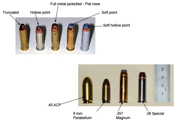
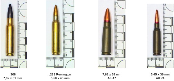
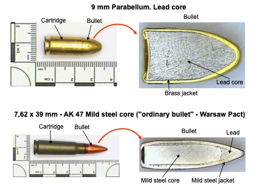
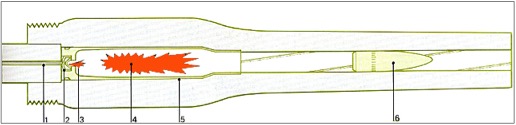
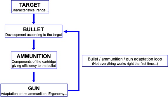
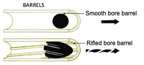


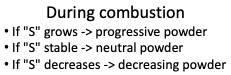
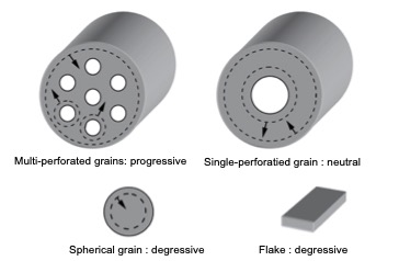
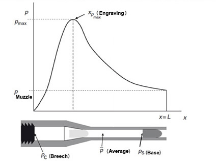
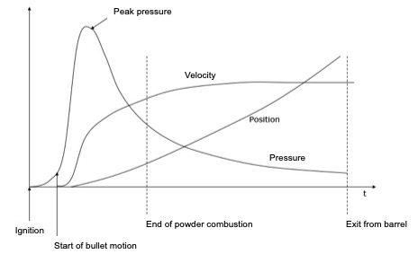
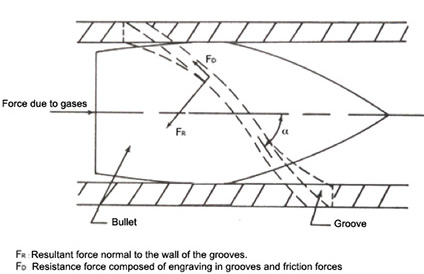
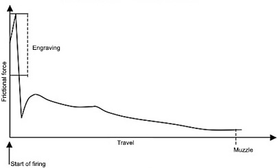
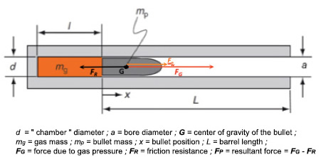
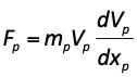
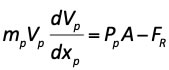
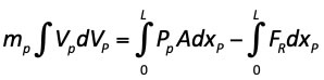
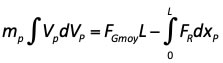
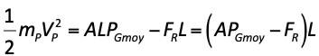
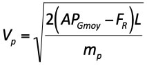
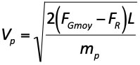
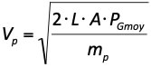
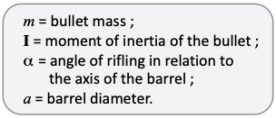
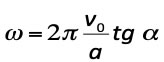
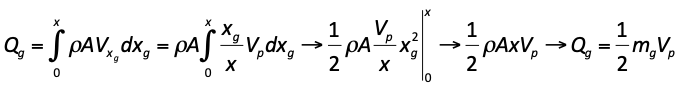
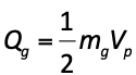
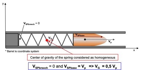
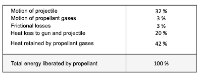
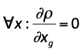
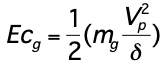
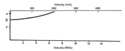
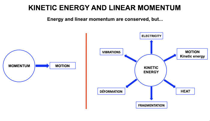
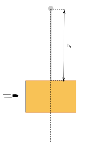
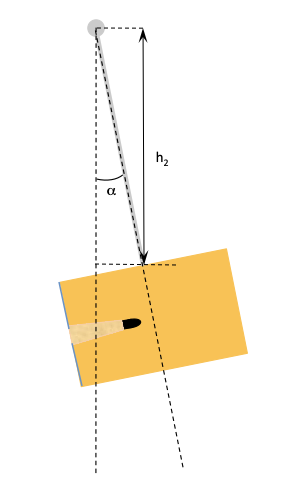


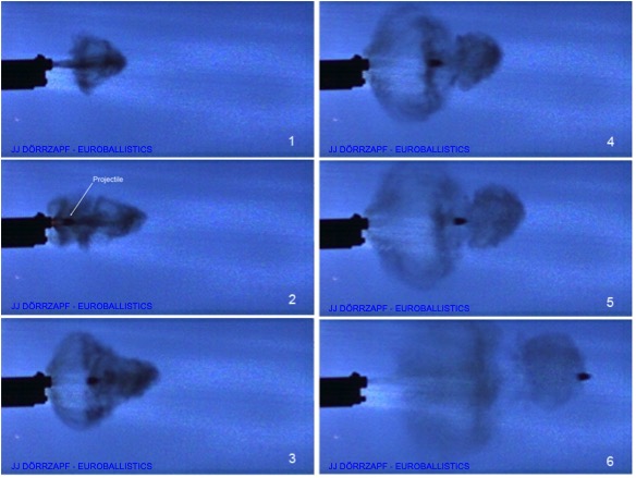
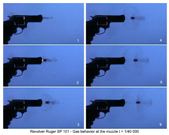
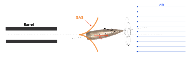
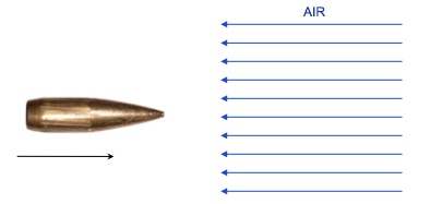
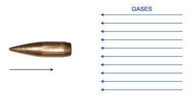
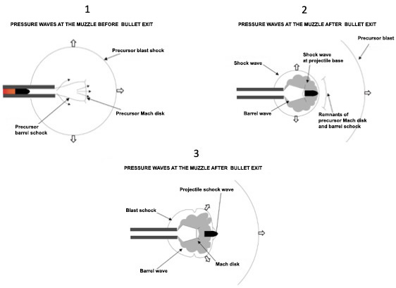
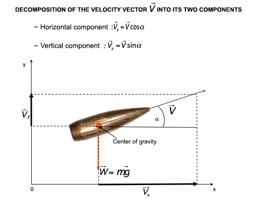
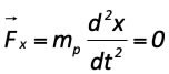
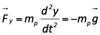
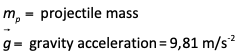
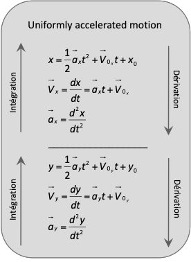
_vide.jpg)
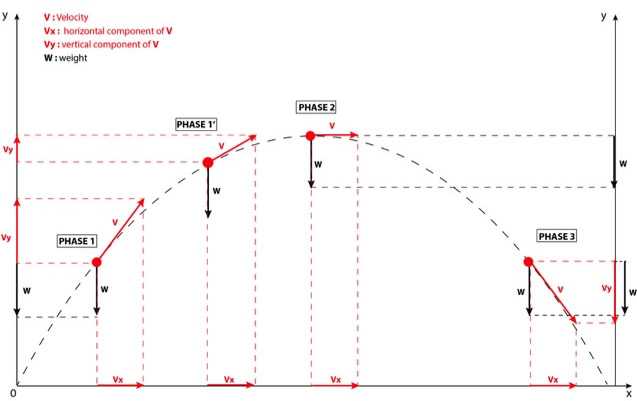
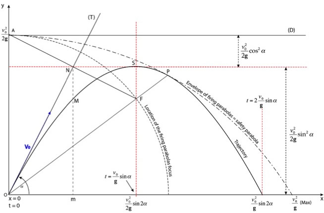
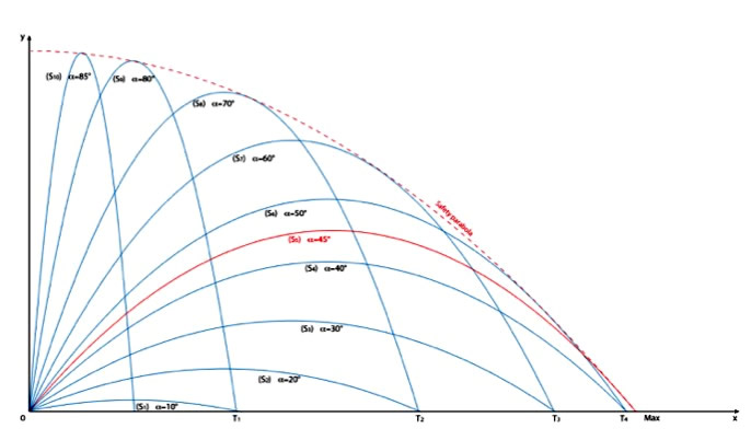
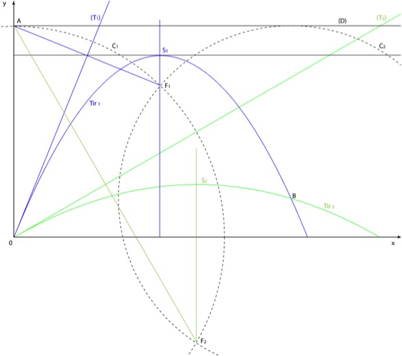
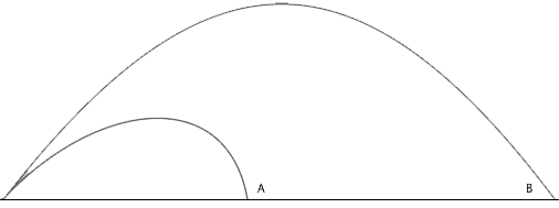

.jpg)