Ce site utilise les fonctionalités de Google Analytics afin de réaliser des statistiques sur les pages consultées et de détecter les éventuels dysfonctionnements. En continuant votre navigation vous acceptez que des fichiers témoins "cookies" puissent être déposés sur votre système (en savoir plus).
Cependant, ce site fonctionne parfaitement sans fichiers témoins. Vous pouvez donc les désactiver.
This presentation focuses on small-caliber firearms. It is intended to be general in nature, so no specific weapon will be discussed. The aim of this document is simply to clarify a few concepts that appear here and there when people talk or write about this type of weapon.
No presentation, however brief, can begin without a brief allusion to the past, since today's techniques are nothing more than the fruit of earlier achievements.
The first firearms appeared in the early 14th century and appear to have been cannons first used in France, as we saw in the "Histoire de la balistique" page, by the English at the battle of Crécy (1346).
These were large tubes, often made of bronze, open at one end only, which were loaded through the mouth. At the other end was a small orifice (the light) through which a servant communicated fire to the powder, using red-hot iron or incandescent coal.
It was probably the slow-burning cord that, used as a means of ignition, enabled the creation of lighter firearms, served by a single shooter whose hands were free to aim.
One end of the wick was attached to an arm, which soon took the shape of an "S" (serpentine). Rotation of the arm brought the glowing end into contact with the powder pan.
All gunmaking research has focused on increasing weapon precision, firing reliability and rate of fire.
Originally, guns were muzzle-loaded. Not only was this a slow process, it also meant using projectiles slightly smaller in diameter than the barrel. Although ingenious processes were invented to allow projectiles to increase in diameter under the thrust of the gunpowder, the precision of the firearms was mediocre.
• Developments
- The barrel rifling
The first rifled barrels appeared around 1476 (helical rifling) and 1498 (rectilinear rifling). The aim was to impose or prevent rotation of the spherical projectile. In a smoothbore gun, friction between the bore and the projectile causes the latter to rotate, resulting, in the air, a trajectory outside the firing plane, i.e. a deviation, when the projectile interacts with the air. This phenomenon is known as the MAGNUS effect. Given the lack of precision in barrel and projectile manufacturing methods, friction is not the same for every shot, and neither is bullet deflection. Hence the idea of either imposing rotation by means of helical rifling, to be taken into account in the sighting system, or preventing rotation by means of rectilinear rifling.
- Loading small arms through the breech
At the same time, breech-loading guns were beginning to appear. However, as the holster did not yet exist, operation was hazardous. Next came firearms with removable chambers that had to be pre-loaded.
- Firing systems (wheelock, flintlock)
The wheellock first appeared in Nürenberg around 1517. By rubbing against a flint, a wheel creates a spray of sparks that ignites the gunpowder.
A little later (around 1610), the flintlock, derived from earlier models (chenapan and miquelet locks), made its appearance. The hammer, to which a piece of flint is attached, rotates the "pan cover", then known as the firing pin, igniting the powder in the process.
English flint blunderbuss dating from the 18th century
• Percussion firearms
They first appeared in the early 19th century. The impact of the hammer on mercury fulminate placed at the orifice of the light caused the powder to ignite (Reverend Fortsyth - 1793). This led to the idea of enclosing the mercury fulminate in a capsule, the forerunner of the modern primer.
With breech-loading having made great progress, the first cartridges in which the primer is housed, initiated by percussion on a needle, appeared (Pauly - 1808).
This idea was perfected by Dreyse in 1838, who invented the first needle-action rifle with a breech that locked by rotation. The cartridge consisted of a cardboard box containing the bullet with its primer on the back and the powder charge. The gun's needle pierces the back of the cartridge, passes through the powder and strikes the primer. This weapon presents a number of problems (breech sealing, since the cartridge is entirely combustible, corrosion and firing pin breakage) which, at first, somewhat obscure the interest of such a principle. But the idea was launched and would soon gain ground.
•Repeating firearms
They first appeared in the early 16th century. They are revolver or multi-barrel firearms. The absence of a reliable firing system blocked their development for a time.
After this rapid overview of the past*, let's move on to more recent firearms which, let's not forget, are nothing more than an evolution of the systems we've just seen.
The field of armaments includes firearms and ammunition which are numerous and varied. It's a complex subject. Especially since the nomenclatures and designations do not always follow a logical approach.
II - FIREARMS : SIMILARITIES AND DIFFERENCES
Since all firearms are designed to fire projectiles, it's only natural that there should be some similarities between them. On closer analysis, however, there are significant differences in their operating principles. Let's start with the basic operating principle of a firearm.
II-I - BASIC PRINCIPLES OF A FIREARM
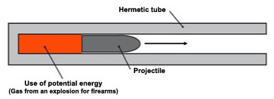
• A firearm is above all a tube open at one end (in general).
Whatever its type and external shape, a firearm consists of a barrel, which is nothing more than a tube open at one end to let the projectile out. The opposite end, called the "chamber", is where the propellant powder explodes. The rear of the chamber is closed by a metal part, the breech. On modern small-calibre guns, this part of the barrel is mainly sealed by the ammunition case.
Simplified principle of a firearm
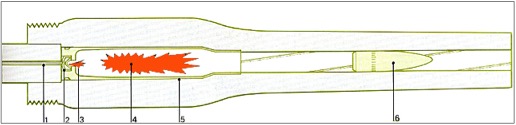
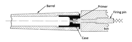
The figure below shows a schematic of a modern weapon.
1) Firing pin - 2) primer - 3) flame jet from primer - 4) ignited powder - 5 case - 6) bullet
From : "Munition für Leoichtwaffen, Mörser
und Artillerie". Ian V. Hogg.
Motor Buch Verlag.
II-II - FIREARMS : SIMILARITIES
• Despite their apparent differences, all firearms have some essential points in common
This is hardly surprising, given that all firearms are designed to fire projectiles.
On
trouve sur pratiquement toutes les armes à feu
les éléments suivants :
A tube : they have a tube open at one end, known as the barrel. This serves as a guide for the projectile, enabling the gas thrust to be correctly applied to the projectile, thus transmitting the acceleration required to reach the desired muzzle velocity. It can also be used to rotate the projectile along its longitudinal axis for gyroscopic stabilization ;
A chamber : opposite the open end of the barrel. This is the thickest part of the barrel, where the greatest gas pressure will be exerted. It must be leakproof either on its own, or in synergy with other parts of the weapon or ammunition, notably the case. It's worth noting that for internal ballistics specialists, a chamber is larger in diameter than the barrel. This is the case for powerful firearms such as long guns and rare handguns that fire cartridges with bottlenecked cases ;
A movable bolt : which closes the rear of the chamber during firing and allows reloading through its opening. On revolvers, there is no breech, but rather a rampart to absorb the impulse transmitted by the holster base when the shot is fired ;
A magazine : which contains the cartridges. To increase the rate of fire, cartridges must be immediately available. This is achieved by integrating them into the weapon via a magazine, a component part of the weapon, or by using a detachable magazine. The simplest firearms have no magazine and are not designed to use a detachable magazine ;
A grip : on some guns, there are two. In this way, it can be held with both hands to increase recoil control and improve accuracy. ;
A trigger : is the external part of the trigger mechanism. It is on this part that the action of the index finger will be exerted in order to provoke the start of the shot ;
Sighting devices :as their name suggests, they allow you to take aim in order to send the projectile where you would like it to go.
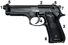
The two images below show the main similarities between handguns, which can lead to some confusion.
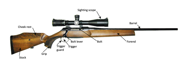
A stock : which is supported by the shoulder to absorb the recoil impulse. These firearms are called rifles or shotguns. Carbines are classically lighter and less powerful than rifles.
Rifle with scope
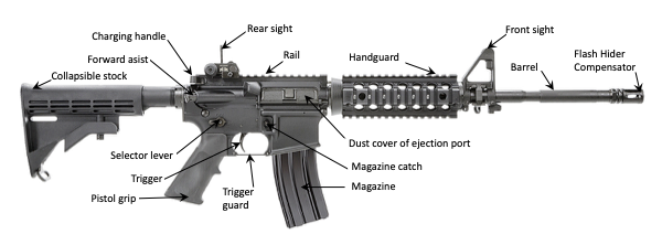
M 16 assault rifle.
.223 Rem. caliber (5.56 mm)
Most of today's manually or automatically repeating firearms are equipped with :
A magazine : fixed to the weapon (cylinder, vertical or tubular magazine) or removable (magazine). They are used to increase the rate of fire by firing successive shots from several cartridges..
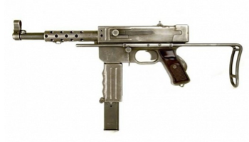
Between pistols and revolvers and rifles are firearms of intermediate size and power: machine pistols and versions of compact firearms.
French MAT 49 submachine gun
9x19 mm Parabellum caliber
Modern compacts
Heckler & Koch assault rifle
.223 Rem caliber (5,56 mm)
FN Herstal. P 90 submachine gun
5,7 x 28 mm caliber
II-III - FIREARMS : THE DIFFERENCES
The first notable difference between firearms concerns their dimensions and the way they are held. This distinction leads to two categories of firearms: handguns and long guns.
• Handguns
The first distinction is simple. A weapon that can be used with only one hand (in the fist) is a handgun. However, there's nothing to stop you using both hands. Two-handed shooting methods have been around for a long time, and form part of the training of armed forces and law enforcement officers. Two-handed shooting is also used in sports. Typical handguns are pistols and revolvers.
Handguns
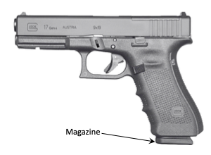
Glock 17 semi automatic pistol
9x19 mm Parabellum caliber
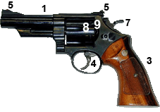
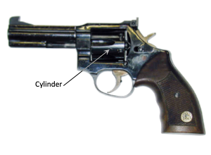
Manurhin MR 73 Revolver .357 Magnum caliber
The two images above show the difference between a pistol (left) and a revolver (right). An automatic or semi-automatic pistol has a magazine containing the cartridges. It is generally housed in the grip. A revolver has a cylinder which is a revolving magazine, hence its name from the American "to revolve", itself coming from the Latin "revolvere", to turn backwards.
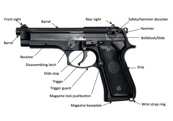
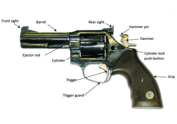
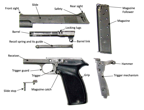
With this initial distinction between pistol and revolver established, let's go into a little more detail. The two images below give a brief nomenclature of the parts making up a semi-automatic pistol and a revolver..
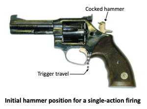
Depending on the weapon, the trigger mechanism allows either single-action or single- and double-action firing. For the shooter, the difference lies in trigger travel and weight. Trigger travel is the distance the trigger must travel from its rest position before firing. Trigger weight defines the force the shooter's finger must apply to the trigger to fire the shot.
- Single action firing
In this firing mode, the hammer is cocked. Pulling the trigger releases the hammer, which strikes the cartridge primer and starts the shot. In single action, the trigger travel is short and the force to be applied (the weight of the trigger) is low or very low, sometimes of the order of 1.5 kg, since all that's required is to release the hammer cocking detent from the trigger head. The finger is placed on the trigger only when you decide to fire. If you change your mind, you remove your finger from the trigger. This is a good habit to avoid setbacks.
By extension, any percussion system in which the hammer is cocked before firing operates in single action.
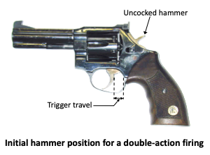
- Double action firing
In this firing mode, the hammer is initially in the down position. The action of the finger on the trigger triggers a number of events: backward rotation of the hammer, compression of the percussion spring. Depending on the type of safety device, the percussion and shock safety elements are progressively removed, or the transmission bar is inserted between the hammer and the heel of the firing pin. When the required angle of rotation is reached, the hammer is released and strikes the cartridge primer, either directly or by striking the firing pin heel. In this firing mode, the trigger stroke is long and the trigger weight high, since the percussion spring has to be compressed until the hammer or hammerhead is released. In double action, the force to be applied to the trigger to initiate a shot can be as much as 5 kg, particularly on revolvers used by public authorities, since a high trigger weight is considered a safety feature. Although the trigger weight is greater in double action than in single action, the finger only comes into contact with the trigger tail once the decision to fire has been made.
For a long time, single-action and double-action firing were the only characteristics of revolvers. Originally, semi-automatic pistols could only fire in single action. Since then, the ability to fire in double action has been implemented in many modern semi-automatic pistols. It should be noted, however, that in the case of semi-automatic pistols, double-action firing requires prior loading of the weapon and, in the case of successive shots, only the first cartridge is fired in double-action, since the hammer is previously at the firing point. The other cartridges are fired in single action, as the hammer has been placed in the cocked position by the rearward movement of the bolt during the previous shot. This situation can be disadvantageous, as the shooter, switching from double action on the first shot to single action on subsequent shots, has to cope with a significant difference in trigger travel and weight, which would require him/her to reposition the weapon if he/she had the time.
The two images below show two revolvers with the hammer in position for single and double action.
• Long guns
More powerful, long guns have a recoil that is no longer acceptable with one or even two hands, and require support from a part of the body. In the end, the shoulder was the most practical choice. The mass of the trunk absorbs relatively well the amount of movement of the weapon when the shot is fired, and the proximity of the eye allows aiming. Naturally, these firearms are referred to as long guns. They are fitted with a stock that rests not actually on the shoulder, but in the hollow between it and the thorax. This type of weapon includes rifles, carbines and even machine pistols, whose burst fire is best controlled when resting on this anatomical region.
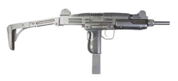
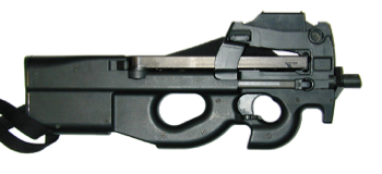
Long guns
Colt M4-A1 assault rifle .223 Remington caliber
Hand-operated repeating rifle
UZI submachine gun - 9x19 mm Parabellum caliber
FN Herstal P90 submachine gun - 5,7x28 mm caliber
• Firearm loading modes and rate of fire
The way in which ammunition is loaded into a weapon is an important factor in its effectiveness, since it determines its rate of fire. The rate of fire corresponds to the number of shots the weapon can fire in a given period of time, usually a minute. We speak of "shots per minute". If we wish to characterize a weapon's efficiency in terms of the number of shots it can fire in a minute, we need to define two rates of fire: the theoretical rate of fire and the practical rate of fire.
The theoretical rate of fire corresponds to the number of shots the weapon can mechanically fire. The practical rate of fire takes into account the gun/shooter pairing and the accuracy of target shooting, which generally requires re-sighting after each shot or burst. The practical rate of fire is always lower than the theoretical rate.
The rate of fire of firearms has evolved considerably, from the 2-3 rounds per minute of Napoleonic-era rifles to the 3900 rounds per minute of the 30 mm GAU 8 Avenger cannon..
The loading mode is an important, if not essential, factor in weapon efficiency. There are four classically defined loading modes :
Single-shot firing ;
Manual repetition firing ;
Semi-automatic firing ;
Automatic or burst firing.
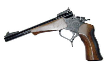
- Single-shot firing
This type of loading is used for single-barrel firearms without a magazine, which must be reloaded manually after each shot. This is the case with some shotguns and handguns, as shown in the image below.
Contender - Single-shot pistol with interchangeable barrel
After each shot, the barrel is tilted, the case ejected, a cartridge inserted, the barrel closed and another shot fired. At the shooting range, this sequence of operations takes time, what's more if the stress of combat is added to the mix?
- Hand repeating firing
Hand repeating firing is an evolution of the previous loading method. These firearms are fitted with a mobile breech operated by the shooter. They are supplied by an internal magazine or a removable magazine containing the cartridges. The shooter's action is limited to loading the weapon once it has been loaded. With the bolt in the rear position, the shooter pushes the bolt forward, using the bolt lever, to close and lock it. As it moves forward, the breech pulls the first cartridge into the chamber. The space in the magazine vacated by the first cartridge is immediately occupied by the second cartridge, which rises under the action of the elevator spring and comes to rest under the breech. This is the first half-transport. Once the shot has been fired, the shooter unlocks the breech and pulls it back, extracting the fired cartridge case. The cartridge, which was resting under the breech, is released, rises and comes into contact with the feed lips of the magazine. This is the second half-transport. The cycle can begin again.
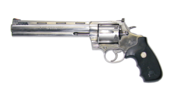
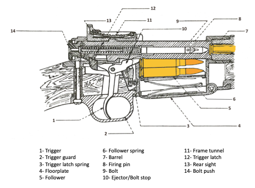
The three images below show two examples of hand-repeating firearms: a revolver and a rifle, and the arrangement of cartridges in the rifle magazine.
Colt "Anaconda" revolver - .44 Magnum caliber
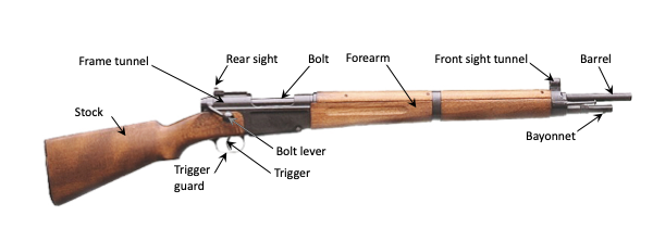
French hand-operated repeating rifle " MAS 36" - 7,5x54 mm caliber
MAS 36 french rifle mechanism and cartridge arrangement
- Semi-automatic firing
In this operating mode, part of the feeding cycle is delegated to the weapon itself, using the energy of the ammunition. This mode of operation offers at least two advantages. The first is that the shooter no longer needs to manipulate the breech, and remains in the firing position. The second advantage is that the feed cycle is much faster without human intervention. It should be noted, however, that snipers still use hand-repeating rifles for precision shooting. The rate of fire is sacrificed for the sake of precision.
In semi-automatic mode, loading the first cartridge requires the shooter's action on the bolt, or on the moving assembly if there is an operating part. Once the first cartridge has been loaded manually, the shooter's action is limited to triggering the shot by pressing the trigger. The entire feeding cycle is carried out automatically by the gun itself. Each time the trigger is pulled, a single shot is fired until the cartridges in the magazine are exhausted. Although the feeding cycle is automatic, a weapon with this operating mode is said to be semi-automatic, as the shooter must pull the trigger for each shot fired. This weapon cannot fire in a continuous burst. A distinction is therefore made between semi-automatic firearms that reload automatically but fire only one shot at a time, and automatic firearms that fire in bursts.
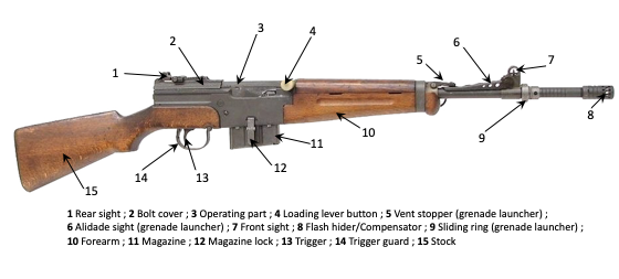
French MAS 49 modified 56 semi-automatic rifle
- Automatic or burst firing
This mode of operation is unique to burst-firing firearms. As long as the shooter pulls the trigger, one shot follows another until the magazine is empty. Some firearms, by design, can only fire in bursts. Others, generally more modern, feature a firing mode selector which, in most cases, allows a choice between single-shot, three-round burst and continuous burst firing. Automatic firearms are fed by magazines or belts, to minimize the time between two supply phases.
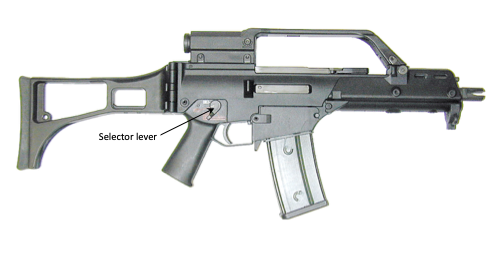
The two images below show the old French MAT 49 machine pistol firing only in bursts, and the H&K G36 assault rifle featuring a firing mode selector.
French MAT 49 submachine gun
9x19 mm Parabellum caliber
H&K G36 5.56x45 mm assault rifle with firing mode selector switch
III
- FIREARMS OPERATING MODES
There are many principles of gun operation, and their mechanisms are limited only by the ingenuity of the designers. In what follows, we will confine ourselves to presenting the most common systems found on small-calibre firearms.
The first guns were single-shot firearms with no magazine. They were only capable of firing a single shot between manual reloads.
One of the factors in a weapon's effectiveness was its rate of fire, so magazines were soon added to allow more shots to be fired between reloads.
Feeding the weapon, which requires motive power, was carried out by the shooter, using his or her muscular strength (hand action on the bolt, finger action on the trigger tail in the case of a double-action trigger, etc.). These firearms are hand-repeating.
In order to increase the rate of fire, feeding mechanisms have been invented that use part of the gas energy generated by the propellant powder as a driving force. These are automatic firearms firing in bursts, or semi-automatic firearms firing one shot at a time.
For an automatic or semi-automatic firearm to function correctly, there must be a certain delay between the projectile being set in motion and accelerated by gas pressure, and the start of the following feed cycle: unlocking, opening the bolt. In other words, you need to give the projectile time to leave the barrel before starting the subsequent operations that will enable the next shot to be fired. If the bolt were to open too soon, some of the gas would escape through the rear of the barrel, causing a drop in barrel pressure. The projectile would not reach its nominal muzzle velocity, and could even get stuck in the barrel. From the shooter's point of view, an accidental return of gas when the bolt is unexpectedly opened is not a pleasant experience.
This delay, which must be respected between the projectile's exit from the barrel and the start of the next feeding cycle, has led to the development of different methods of using the gas motive force, depending mainly on the weapon's power.
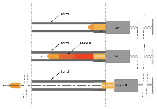
• Simple blowback
- Low-power firearms
On low-powered handguns, the gas vein in the barrel acts directly on the bolt, via the holster base. On low-power handguns (.22, 6.35 mm, 7.65 mm), the inertia of the bolt and the force of the energy recovery spring are sufficient to allow the projectile to leave the barrel before opening, i.e. before the barrel and bolt separate. Once the projectile has left the barrel, the bolt continues its recoil movement under the impulse transmitted to it by the gases. The cycle of extraction, ejection from the case and then feeding begins.
The diagram below shows the principle of direct gas action.
DIRECT GAS ACTION
- More powerful firearms
If the weapon's dimensions permit, it is possible to increase the mass of the bolt, which then becomes a percussion part. This is the case, for example, with the French MAT 49 machine pistol in 9 mm Parabellum caliber, whose bolt is a machined steel part weighing just over 500g. When the shot is fired, the inertia of the bolt is such that it has only travelled a fraction of the cartridge length backwards before the projectile leaves the barrel.
On handguns of 9x19 mm Parabellum caliber and above, the inertia of the bolt, supported by the force of the energy recovery spring, is no longer sufficient. It is necessary to delay the separation of the barrel from the bolt. To this end, the barrel and bolt are locked together. During the acceleration phase of the projectile in the barrel, the barrel-bolt assembly begins to move backwards. After a few millimeters of travel towards the rear of the bolt, the projectile has had time to exit the barrel. At this point, separation of the barrel and bolt (opening) can take place, after unlocking. The bolt continues to recoil on its own, starting a new feeding cycle. The barrel will have accompanied the bolt for a brief moment, over a short distance, during the initial phase of firing. This is known as the "short barrel recoil".
The diagram below shows the principle of short barrel recoil.
DIRECT GAS ACTION WITH SHORT BARREL RECOIL
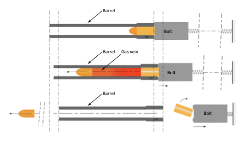
The video below shows the phases of a feed cycle for a 9 mm Parabellum semi-automatic pistol.
DIRECT GAS ACTION WITH SHORT BARREL RECOIL
Percussion takes place at time t0. Between t0 and t1, the projectile travels down the barrel and the barrel-bolt assembly begins to move backwards, in accordance with the principle of conservation of momentum. At t1, the projectile leaves the barrel and the barrel and bolt assembly continue to move backwards until time t2, when unlocking and opening takes place.
Example of two mechanisms for short barrel recoil
To conclude this section on short barrel recoil, we offer two examples of mechanisms that perform this function.
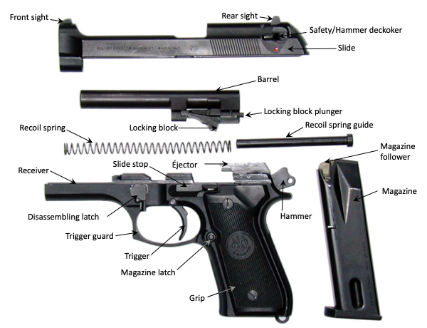
The system used in some Beretta pistols
Beretta 92 FS semi-automatic pistol, 9x19 mm Parabellum caliber, disassembled
The picture above shows a disassembled Beretta 92 FS pistol. The parts to be considered for the barrel recoil system are the locking block and the locking block plunger. During the initial phase of recoil, the locking block secures the barrel to the slide.
In the picture, the locking block is free and in the down position. When the firearm is in use and before firing, the locking block, forced by the receiver, is in the up position. Its lateral locking lugs are in place in two recesses on the inside of each side of the slide, ensuring that the slide and the barrel are locked.
At the start of the shot, the barrel and slide recoil. After a stroke of 9 millimeters, the heel of the locking block plunger comes to rest on part of the receiver. The locking block plunger is thus blocked, and its head comes into contact with a ramp machined into the locking block, forcing it down. The lateral lugs come out of their seats on the slide, unlocking the barrel from the slide.
The oscillating barrel system
Oscillating barrel system
This system is used on the French MAC 50 semi-automatic pistol, shown disassembled in the image below.
MAC50 9x19 mm Parabellum semi-automatic pistol, disassembled
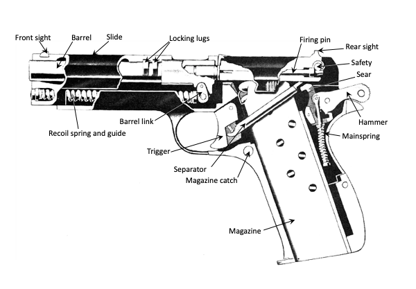
The diagram below shows the MAC 50 pistol in firing configuration.
MAC 50 pistol in firing configuration
The barrel is connected to the receiver by the barrel link, which is attached to the receiver by the slide stop axis. Before firing, the barrel and slide are locked together by the barrel locking lugs, which are engaged in their seats on the slide.
When the shot is fired, the barrel and slide assembly moves back and the barrel link begins to rotate around the axis of the slide stop. This rotation lowers the rear of the barrel and, after a stroke of 8 mm, releases the barrel locking lugs from their seat on the slide. The barrel and slide are then disengaged.
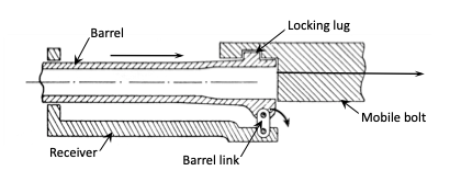
- On even more powerful firearms
The principle of direct gas action via the case base can be applied to more powerful firearms, such as those firing 7.62 mm NATO ammunition. A good example is the French automatic firearm model 1952 firing 7.5 mm ammunition (AA 52) or the automatic firearm caliber 7.62 NATO model F1 (AA 7.62 N - F1). These are the same weapon, but the one firing 7.5 mm ammunition (AA 52) was in service in France when the country was not a member of NATO. On this weapon, the system enabling the projectile to leave the tube without gas return at the bolt uses a lever mechanism. It is more complex and merits further analysis.
The bolt is made up of two parts: a front part, called the mobile head, and a rear part, called the mobile bolt, which acts as a kind of additional mass. Under the effect of gas pressure, the force exerted by the base of the case on the front part of the bolt, the mobile head, causes the latter to recoil immediately, but this movement is slowed by a lever mechanism.
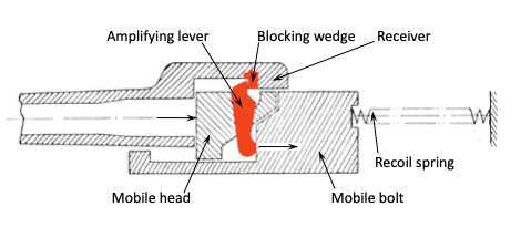
The figure below shows a schematic diagram of the system.
DIRECT GAS ACTION WITH SLOWED OPENING
When the shot is fired, the bolt head (mobile head) immediately moves back. As soon as the amplifying lever rests on the blocking wedge fixed in the receiver, it sets the mobile bolt in motion. For every x mm travelled by the mobile head, the mobile bolt moves back ax mm, a being the amplification ratio. The amplification ratio is not constant for each millimeter travelled, but averages 4. When the amplifying lever is released, the bolt moves back at the same speed as the mobile head.
Contrary to what can be found in manuals and technical guides, there is no delay in opening, which occurs as soon as the mobile head is subjected to the force of the gases transmitted by the case base. Opening is just slowed down.
The mobile bolt, acting as an additional mass, is solicited in its rearward movement by a force attenuated in the inverse ratio of the lever arms. The lever amplifier is often mistakenly referred to as the inertia amplifier lever (LAI). Since inertia is linked to mass, and the mass of the mobile bolt is obviously constant, it cannot be amplified. A better term would be : recoil amplifier lever.
• The indirect action of gases. Gas-operated firearms
In this mode of action, the gases do not act directly on the bolt via the holster base, but rather indirectly. Part of the gas is taken from a point on the barrel and exerts a mechanical action at a distance. The bolt remains locked on the gun's frame relative to the barrel until the pressure reaches the gas take-off point. In this case, the system is referred to as a locked bolt system, as opposed to a non-locked bolt system that uses the direct action of the gas stream.
Gases can be taken from various points on the barrel :
- at the rear of the barrel ;
- at the muzzle ;
- between muzzle and breech.
- Taking gas from the rear of the gun
This system, used in particular on the Roth pistol, is rarely used. It requires a specially-organized primer case. After percussion, the primer, subjected to gas pressure, recoils and, acting as a piston, forces the firing pin backwards. The firing pin then unlocks the bolt.
The diagram below illustrates the principle.
TAKING GAS FROM THE REAR OF THE BARREL (Système Roth)
- Taking gas from the barrel's muzzle
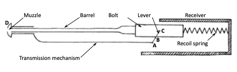
When they reach the muzzle of the gun, the gases have the same velocity as the projectile. The principle is equivalent to that used for the muzzle brakes on artillery barrels, but the forward-directed force of the gases is used to unlock and recoil the bolt.
The figure below shows this principle, which was first used on the French Puteaux 1905 machine gun.
When the gases reach the muzzle of the barrel, they interact with device D, inducing a forward force transmitted at A to a lever attached to the bolt at C, which, by rotating along axis B, unlocks and retracts the bolt.
TAKING GAS FROM THE BARREL'S MUZZLE (French Puteaux 1905)
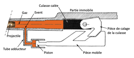
- Taking gas between muzzle and breech
TAKING GAS BETWEEN MUZZLE AND BREECH
This is the most commonly used principle. A hole, calibrated by a vent made of corrosion-resistant material, is drilled in the barrel. Once the projectile has passed through the vent, some of the gas is released. Two devices can be used. Either the gases are fed through a long tube to the release mechanism (direct impingement), or they are fed through a short tube to a cylinder containing a long piston acting at a distance to enable release (gas piston). This principle is also the basis, for more powerful firearms, of more complex mechanisms with several pistons or two vents, for better balancing of forces and greater weapon precision.
IV - AMMUNITON
There are many different types of ammunition. Their names often follow no logic. Identical ammunition may be called by different names. The actual caliber is sometimes quite different from that of the commercial name. Once again, we'll confine ourselves to the broad outlines and common features of modern ammunition.
• Cartridge
The various components used to propel a projectile are encapsulated. A modern cartridge, irrespective of its caliber, is presented, with a few possible variations, according to the diagram below :
1
: Bullet - 2 : Case - 3 : Powder - 4 : Primer
The cartridge shown above is a rifle cartridge. The shape of its projectile and case, as well as their dimensions, vary according to the weapon for which it is intended. However, the basic components are always the same :
Bullet ;
Case ;
Propellant powder ;
The primer to ignite the gunpowder ;
• Different types of projectiles
The "ordinary" bullet for NATO forces consists of a lead core encased in a metal jacket, generally brass (full metal jacketted bullet). To enhance the bullet's penetration performance, a steel insert (hard core) can be placed in its center. Other types of armor-piercing projectiles also exist, of course.
If, on the other hand, you want the bullet to stop more quickly in the target, you make it easier to expand. To this end, part of the metal liner is always left in place to ensure a good rifling grip in the barrel, but the end is modified so as to leave the lead bare ("soft point" bullet). The latter, a relatively soft material, deforms easily and facilitates the desired expansion. A cavity at the tip ("hollow point" or "soft hollow point" bullet) further enhances expansion capacity.
The image below shows a number of bullets with different targeting behaviour. .
DIFFERENT BULLETS : DIFFERENT EFFECTS
* The bullets shown above are not to scale.
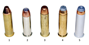
• Cartridges for handguns
Below are a few variations of revolver cartridges with bullets corresponding to the desired effects on target.
Truncated bullet ;
Hollow-point bullet ;
Flat-nose bullet ;
Soft-point bullet ;
Soft-hollow-point bullet.
IThese are cartridges designed to be fired in revolvers (bead at the bottom of the case). There are exceptions, however, such as the "Desert Eagle", a semi-automatic pistol sold in a version capable of firing this ammunition. All are .357 Magnum cartridges, except (2), which is .38 Special (shorter). Bullets have differences in their heads, resulting in different target behavior.
The same bullet variants can be found on cartridges for automatic reloading firearms, provided that the ogives are suitable for interaction with the feed ramp.
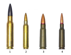
• Cartridges for long guns
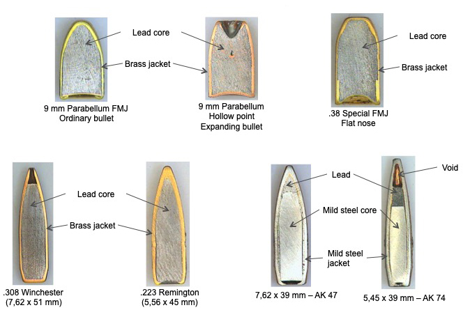
Listed below are cartridges designed to be fired in long automatic or semi-automatic repeating firearms (rifles, assault rifles). All three feature a fully jacketed projectile to comply with the Hague Conventions.
From left to right is a cartouche of :
7,62 x 51mm OTAN (.308);
5,56 x 45mm OTAN (.223 Remington) ;
7,62 x 39 mm (AK 47), former Warsaw Pact ;
5,45 x 39 mm (AK 74), former Warsaw Pact ;
Cartridges for Nato (1, 2) and former Warsaw Pact (3, 4) forces long arms
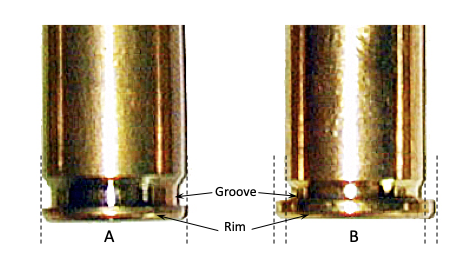
• Rimmed and rimless cases
Case bases must be adapted to the extraction system of the firearm for which they are intended. On small-caliber firearms, there are two main extraction systems, analyzed below. One acts on the case bead, the other on the groove. Each of these elements must be matched to the corresponding mechanism.
Case for automatic reloading firearm Use of the groove for extraction
Case for revolver Use of the rim for extraction
In the image above, we can see that both cases have a groove and a rim. The distinction lies in the dimensions of these two elements in relation to the case diameter. Case A, intended for use in an automatic reloading firearm, has a groove designed to accept the extractor hook. It is wider than that of case B, which has a rim whose diameter is greater than that of the case body and is adapted to the star extractor of a revolver.
• Case extraction. Groove extractor, star extractor
Once the cartridge has been fired, all that's left in the gun is the case, which must first be removed from the chamber. This action is performed by a mechanical part known, quite naturally, as the extractor. There are a number of different extraction systems, and we'll just mention the most common ones.
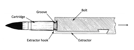
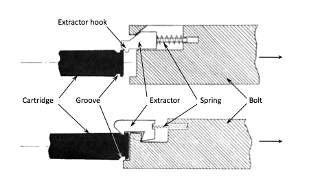
- The groove extractor
The image below shows a schematic of a groove extractor system.
Diagram of a groove extractor system
Other systems are available, of which we present two schematic diagrams below.
Extraction mechanisms with groove extractors
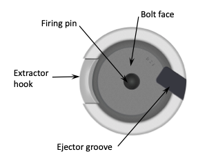
The image below shows a typical bolt head diagram for a groove extractor. The bolt face is where the case base rests.
Schéma d'une tête de culasse
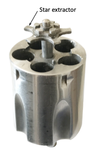
- Star extractor
The image below shows a revolver cylinder and its star extractor.
Cylinder and its star extractor
We can't end this paragraph without mentioning at least two exceptions to the rule. There is a version of the Desert Eagle semi-automatic pistol, designed by Magnum Research in the USA and Israel Military Industries in Israel, which fires ammunition intended for revolvers. Similarly, the French company Manurhin marketed a revolver that came with two barrels, one for conventional revolver ammunition, the other for 9x19 mm Parabellum cartridges.
• Ejection
Once the case has been extracted, it's time to eject it.
Revolvers are loaded by hand. Extractor and ejector are same piece. If you have time, at a sport shooting stand for example, you can remove the cases one by one. If, for some reason, you're in a hurry, simply squeeze the extractor rod and, if necessary, jerk your wrist to eject the cases. On self-loading firearms, once the case has been extracted, it must be discarded, so as not to interfere with the feed cycle. An ejector is therefore essential. As with any mechanism, there are different systems, and we're going to present three of them here.
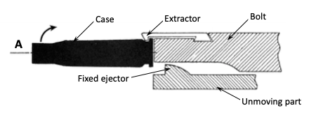
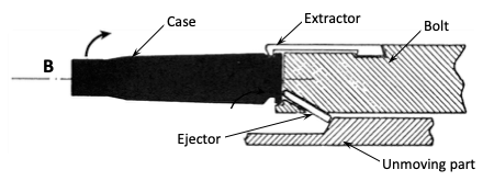
Diagram A below shows a system in which the ejector is fixed to either the frame or the receiver. It is therefore immobile in relation to the recoiling bolt. At a point in the latter's rear stroke, the case base strikes the ejector.
Ejector fixed on the frame or receiver
Diagram B below shows a device in which the ejector is attached to the bolt. When the bolt recoils, the heel of the ejector comes into contact with the stop on the fixed part of the weapon. The ejector head then projects into the bolt face and strikes the case base.
Ejector mounted on the bolt and coming to a stop
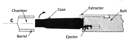
Diagram C below describes a mechanism in which the ejector head, pushed by a spring, always protrudes out of the bolt face. When the cartridge is inserted, it is forced by the firing chamber, forcing the ejector backwards and thus compressing its spring. When the bolt recoils, as the case leaves the chamber, it is expelled under the force of the ejector spring.
Spring-loaded ejector mounted on the bolt
For ejection to be effective, extractor and ejector must apply a couple of forces to the case, one holding it and the other pushing it. The best position for these two parts is diametrically opposite each other in the bolt face, or close to it.
• Centerfire and rimfire cartridges
The propellant powder in the case must be ignited. This is achieved by using an explosive sensitive to friction (mechanical percussion ignition) or to a sudden rise in temperature (electrical ignition). The propellant powder used in small-calibre firearms is ignited by mechanical percussion of an explosive composition. There are two types of firing process : centralfire and rimfire cartridges.
- Centralfire cartridges
The explosive priming composition is placed in a small metal container, the primer. The primer is set in the center of the case base, hence the name centerfire cartridge.
The figure below shows an image of cases with primer crimped onto them. The images on the left and right show Berdan and Boxer primers respectively.
Berdan system on the left and Boxer on the right
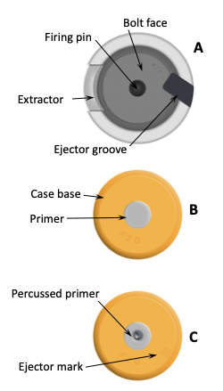
The image below shows the characteristic elements of the central fire firearm.
Central percussion
Drawing A shows a typical bolt face configuration for a centerfire firearm. Drawing B shows the base of a case designed for centerfire, and drawing C shows the same base after the primer has been percussed.
- Rimfire cartridges
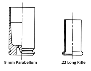
Some ammunition cases have no primer. The inside of the case base is coated with an explosive priming composition. Cases are fitted with a bead, and percussion consists in crushing part of this bead against the rear edge of the barrel. Since percussion takes place at the periphery of the base, this is known as rimfire process.
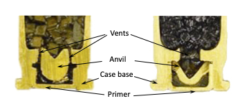
The image below shows a cross-section of two bases, from left to right, for central fire and rimfire cartridges respectively.
Central percussion on the left
Rimfire on the right
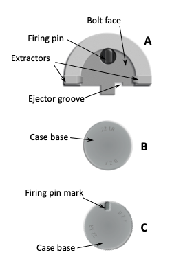
The image below shows the characteristic elements of rimfire firearm.
Percussion annulaire
Drawing A shows the typical configuration of a bolt face on a rimfire weapon. Drawing B shows the base of a case designed for rimfire, and drawing C shows the same case base after it has been fired.
Jean-Jacques DÖRRZAPF
Ancien chef de l'Unité de Balistique Lésionnelle au Centre Technique de la Sécurité Intérieure Expert près la Cour Pénale Internalionale